


Issue Preliminary 2, March 2009 Model 45 User Guide
Page 20 Studio Technologies, Inc.
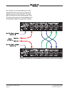
are fully isolated from the 2-wire intercom
circuit. In this situation the Model 45’s only
function is to route, by way of the hybrids,
the 2-wire interface’s audio signals to and
from the 4-wire outputs and inputs. In this
mode of operation the Model 45 acts as a
typical user station on the connected inter-
com circuit.
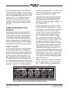
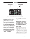
As a connection confirmation, hardware
and software in the Model 45 monitors pins
2 and 3 of the 2-wire (PL) intercom connec-
tors for the presence of DC voltage. A level
greater than approximately 18 volts DC on
pin 2 will cause the status LED labeled
PIN 2 to light. A level greater than 18 volts
DC on pin 3 will cause the status LED
labeled PIN 3 to light.
The author is aware that user intercom
devices almost always draw power from
pin 2 rather than pin 3. However, in many
broadcast applications power is provided
on all intercom paths so that flexible chan-
nel assignments can be made. In the ex-
ternal 2-wire power mode the Model 45
is simply an observer; whether intercom
power is present on pin 2, pin 3, or both
pins 2 and 3 is not significant.
In order that the Model 45’s 2-wire-to-4-wire
interface circuits remain stable and don’t
generate audio artifacts an auto terminate
feature is implemented. This maintains a
200 ohm termination on both pins 2 and
3 as long as neither of the 2-wire power
status LEDs is lit. To clarify, if either or both
the LEDs are lit then both terminations are
removed. It was felt that this method would
provide a fairly accurate indication that an
active intercom circuit is connected. In this
case the 200 ohm termination is expected
to be provided elsewhere, typically as part
of the external power supply, and the Mod-
el 45’s termination is “lifted.”
When the Model 45 is Serving as the
2-Wire Intercom Power Source
When configuration DIP switch 2 is set
so that the Model 45 provides 2-wire (PL)
power its interface supplies 30 volts DC
on pin 2 of the 2-wire (PL) intercom con-
nectors. A maximum current draw of 300
milliamperes is available. This current is
sufficient to power various intercom user
devices such as small user stations and
belt packs. A common broadcast appli-
cation would be to use RTS BP325 belt
packs. Select the connected devices so
that their total current doesn’t exceed 300
milliamperes. That’s not always the easi-
est figure to calculate but a web search
will generally find specifications for all
commonly used devices. For example, a
search finds that the original version of
the BP325 consumes a maximum of 85
milliamperes of current. According to this
figure up to three of these units can be
connected to each Model 45 Interface.
Newer versions of the BP325 use surface
mount component technology and have
a lower maximum current draw of 65 mil-
liamperes. Four of these “modern” BP325
units can easily be supported.
The Model 45’s intercom power supply
circuit operates under software control.
This allows detection of fault conditions
and protection of both the Model 45’s
circuitry and connected intercom user
devices. Upon initial Model 45 2-wire inter-
com power up no monitoring of the inter-
com power output takes place for a period
of five seconds. This allows the Model
45’s circuitry and the connected intercom
user devices to stabilize. The LED associ-
ated with pin 2 will light to indicate that the
output is active. After this initial 5-second
period monitoring becomes active. A fault
condition is detected if the power on