


Model 45 User Guide Issue Preliminary 2, March 2009
Studio Technologies, Inc. Page 23
An auto null sequence begins with the
muting of the 4-wire input and output
signal paths associated with the channel
being nulled. This is followed by a short
period of 24 kHz signal that is sent out
the 2-wire party-line intercom interface
channel. This will turn off microphones
on those connected user devices that
are compatible with the RTS TW-series
“mic kill” protocol. The actual auto null-
ing process is performed next. A series of
tones will be sent out the 2-wire interface.
Other Model 45 circuitry, under software
control, will rapidly perform adjustments
to achieve the best null possible. After the
adjustments have been made the results
are stored in nonvolatile memory. Once
the process is complete the 4-wire input
and output paths are again activated.
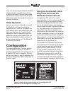
Configuration DIP switch 3 allows an
independent auto null button mode to
be selected. If switch 3 is in its on (up)
position, the front-panel pushbutton will
function in quite a different manner. In the
independent mode, a single “tap” to a
switch will cause channel 1 to auto null.
Two “taps” will cause channel 2 to auto
null. By observing the operation of the two
auto null status LEDs it will become readily
apparent which of the button modes has
been selected.
If possible, prior to performing an auto null
it’s polite to warn all personnel who are ac-
tively using the connected intercom devic-
es. The tones sent to the 2-wire intercom
circuit during the nulling process are not
excessively loud or obnoxious, but most
users might want to remove their headsets
during the process. In addition to warning
users, it might be a good time to ask them
to mute any active microphones. While
the automatic “mic kill” signal will apply
to many user devices it may not apply to
all. Muting microphones is significant as
obtaining a “deep” null requires that no
extraneous signals be present on the inter-
com circuit.
Auto Terminate Disable
As previously discussed in this user guide,
the auto terminate function can come into
play when the 2-wire party-line interface
is configured to not supply power. Using
a combination of hardware and software,
pins 2 and 3 of the 2-wire (PL) intercom
connector are monitored for the presence
of DC voltage. If a level of greater than ap-
proximately 18 volts DC is not detected on
either pin, 200 ohm terminating networks
are applied to those same pins. This en-
sures that the Model 45’s hybrid circuitry
remains stable, preventing objectionable
audio signals from being sent to the 4-wire
output connectors. One caveat does ap-
ply: there may be a few seconds of severe
noise whenever an interface moves from a
DC present condition to a DC not present
condition. But other than that period, the
audio paths will remain “clean.”
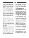
As a visual aid, LEDs on the front panel
will display the DC power status of pins
2 and 3. But when auto terminate disable
mode is active (configuration DIP switch 4
set to on) the LEDs will no longer indicate
the intercom circuit’s termination status.
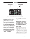
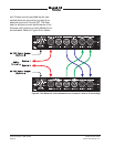
For special applications the auto terminate
function can be disabled. This will primar-
ily come into play when “splitting” the
Model 45’s resources into two separate
single-channel interfaces. Moving con-
figuration DIP switch 4 to its on (up) posi-
tion disables the auto terminate function.
To someone observing only the Model
45’s front panel this change would not be