


Issue Preliminary 2, March 2009 Model 45 User Guide
Page 16 Studio Technologies, Inc.
drop can become appreciable in situations
where belt pack operation wouldn’t nor-
mally be impacted. Performing accurate
calculations in this scenario is a bit more
difficult but might be required to ensure a
reliable installation.
Initial Operation
As soon as a source of power is applied
the Model 45 will begin its power-up
sequence. As a “boot-up” indication the
input power, status, and meter LEDs will
light, one at a time, in a “walk-through”
sequence. After the sequence has com-
pleted, one of the input power LEDs will
light indicating which power source is
actively powering the unit. The Model 45
is now fully functional.
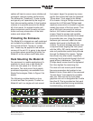
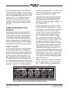
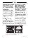
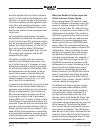
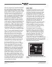
Configuration
To support the needs of various applica-
tions the Model 45 allows a number of
operating parameters to be configured. A
5-position DIP switch assembly, located
on the front panel, is used to establish the
desired configuration. Refer to Figure 6 for
detailed views.
Using the Connected 2-Wire
Party-Line Circuit as the
Model 45’s Power Source
Configuration DIP switch 1 is used to
select whether or not the connected 2-wire
intercom circuit can be used to provide
power for the Model 45. When the switch
is in its off (down) position the intercom
circuit cannot be used to power the Model
45. This ensures that no current will be
drawn from the intercom circuit, some-
thing that can be important if the circuit is
limited in available current, or if the length
of the interconnecting cable is excessive.
When switch 1 is in its on (up) position the
2-wire party-line circuit can serve as the
power source for the Model 45.
It’s important to remember that if an ex-
ternal source of 24 volts DC is connected
it will always be used as the Model 45’s
power source. Even if switch 1 is in its
on (up) position, power will be drawn
from the connected intercom circuit only
if the external source of 24 volts DC is
not present. With that in mind, it’s highly
recommended that unless the application
has been carefully designed, any time an
Figure 6. Details of front panel showing the five configuration DIP
switches and the configuration switches chart