


dmc3-4
www.mssystems.com | 800.421.1587 | www.mssystems.com
Page 20
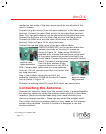
amplifier. From each volume control location, run a MS2SXSC cable to
each satellite speaker (left & right) or mono as shown in Figure 19.
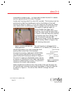
Install the appropriate mounting ring for each respective speaker. Follow
the instructions included with the speaker for specific dimensions on the
mounting ring. Secure the MS2SXSC cable from the speaker’s respective
volume control to avoid drywall damage.
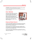
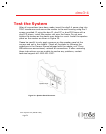
Door Release Options
The door release option is a dry contact closure provided by the dmc3-4
master. This dry contact is rated 24V at 2 Amps. The sample applications
below represent some uses of this option. However, only one application
can be used in any dmc3-4 system at a time.
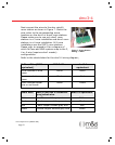
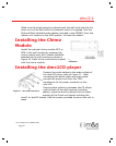
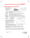
Door or Gate Release Mechanism
Run a single line of PBVM127X1 from the dmc1H or dmc1HC housing to
the door release mechanism. Connect the red and white wires to the two
wire terminals of the door release mechanism.
Run another single line of PBVM127X1 from the dmc1H or dmc1HC
housing location to a gang box next to a 120VAC receptacle where the
remote power transformer (part #240054) will be plugged in. Label and
secure cables at the housing.
The door release switch contacts are very versatile and can be used with
many AC/DC door or switch contacts. Be sure to use the wire and power
supply or transformer specified by the door or gate release product being
used.
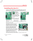
Panic Interface with Security System
Run a line of PBVM127X1 from the dmc1H or dmc1HC housing location to
the security control panel. Setup the security panel to receive a normally
open dry contact for panic operation. (Refer to programming procedures
accompanying the security panel). Label and secure cables at the dmc1H
or dmc1HC housing. Have a certified security installer hook the dmc3-4
up to the alarm system.
$QEG$QEG 1.1.