


dmc3-4
www.mssystems.com | 800.421.1587 | www.mssystems.com
Page 18
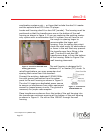
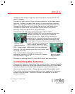
Follow the steps below to attach a NuTone 300 Ohm twin lead antenna to
the dmc3-4.
1. If the antenna has a plug on the end, cut the plug off
2. Strip the 2 wire ends
3. Connect the wire ends to terminal S1 and S2 on the antenna board
4. Connect a bare jumper wire (a 22 gauge speaker wire works well)
between the S3 and S4 terminals.
Follow the steps below to attach a separate AM/FM antenna system with
300 Ohm FM twin lead and orange AM antenna wire:
1. Connect the FM twin leads to terminal S1 and S2 on the board
2. Connect the AM antenna (orange wire) to terminal S4
3. Terminal S3 is not used in this configuration
Follow the steps below to connect a single orange wire antenna system:
1. Connect the orange wire to either S1 or S2. Note do not connect
the wire to both S1 and S2 doing this will short out the FM antenna
signal.
2. Connect a bare jumper wire (a 22 gauge speaker wire works well)
between the S3 and S4 terminals.
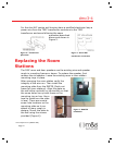
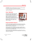
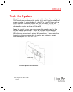
Wireless Remote Control Connection
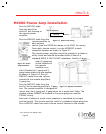
To install the optional wireless remote control receiver module MCRC,
attach the MCRC module using the Velcro strips provided to the wall
housing. Place the white antenna lead through the hole provided in the
wall housing into the wall cavity. Failure to do so may result in poor range
of the wireless remote control system. Connect the wire harness from the
MCRC to the connector labeled REMOTE on the master.
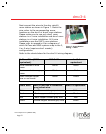
After the master is installed you must program the transmitter. Complete
this step after completing the system test. To program the transmitter
simultaneously press and release the AUTO and SOURCE buttons. The
display will show RF and SET on it. Then press and hold any button on the
remote until the RF and SET disappear from the display. To cancel this
function, simultaneously press AUTO and SOURCE.
$QEG$QEG 1.1.