


dmc3-4
www.mssystems.com | 800.421.1587 | www.mssystems.com
Page 10
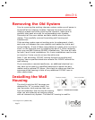
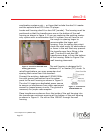
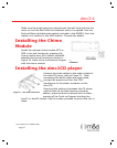
Figure 2 - dmc1H or dmc1HC wall
housing placement
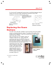
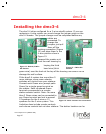
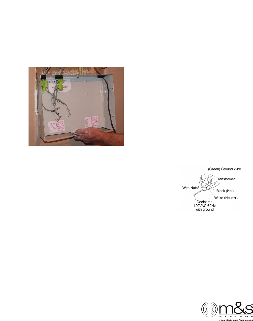
Figure 3 - Transformer
120VAC/60Hz run
combination systems only – or those that include the dmc3-4 master
and the optional dmc1CD 6-disc CD player.
Locate wall housing dmc1H or dmc1HC (combo). The housing must be
positioned so that the transformers are on the bottom of the wall
housing as shown in figure 1. If you are replacing the existing master
only system with a combination dmc3-4 system you will have to cut
the rough-in opening larger to
accommodate the larger wall
housing. Prior to making the cutout
check the stud cavity for obstructions
or items in the wall that may prevent
the transformers from fitting in the
wall. The dmc1H and dmc1HC
transformers drop in from the bottom
of the housing. Refer to Figure 2 for
wall housing placement.
The wall housing is designed to fit
between 16" on center (OC) studs. In
retrofit applications you may encounter stud
spacing that varies from this standard.
Connect the existing, dedicated 120VAC/60Hz
line with ground connection from the power
panel to the wall housing as shown in Figure 3.
The dmc3-4 requires a dedicated power source
to assure no interference from other equipment
caused by looped power circuits. The ground is
necessary for proper radio reception.
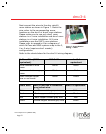
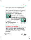
Place transformer enclosure from the inside of the wall housing into
the transformer enclosure opening at the bottom of the wall housing
as shown in Figure 4. Do not run the 120VAC through the wall
housing.
$QEG$QEG 1.1.