


dmc3-4
www.mssystems.com | 800.421.1587 | www.mssystems.com
Page 12
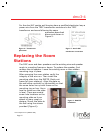
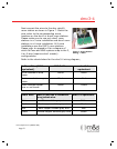
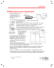
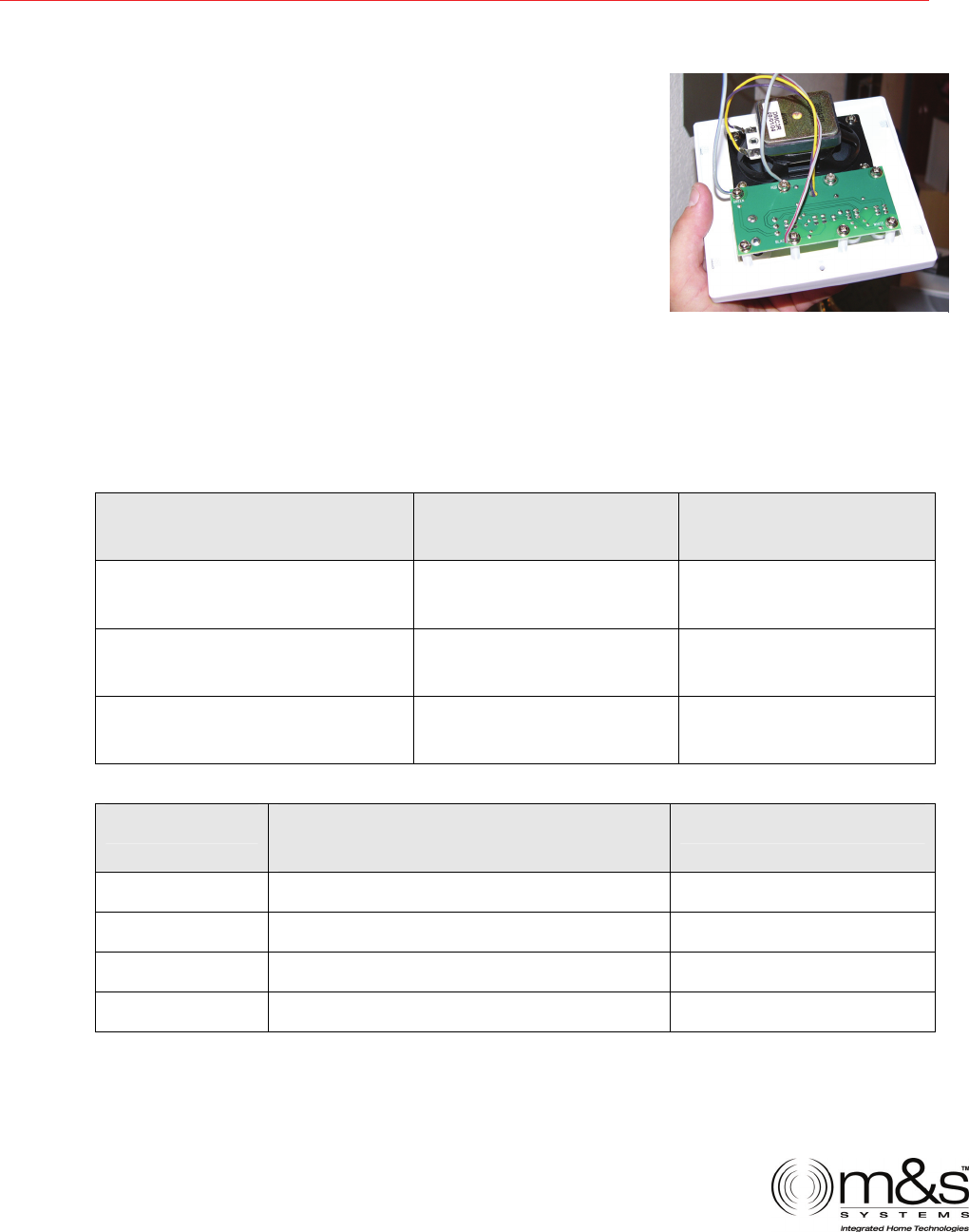
Figure 7 - Room Station
W
iring - 3-
W
ire
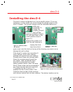
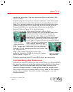
Next connect the wires to the dmc retrofit
room station as shown in Figure 7. Match the
wire colors to the corresponding screw
locations on the dmc3 or dmc4 room stations.
Please make sure to use only dmc3 room
stations in a 3-wire installation and dmc4 room
stations in a 4-wire installation. All 6-wire
installations use the DMC1 room stations.
Please refer to appendix A for a diagram of
which NuTone and M&S systems map to the 3,
4 or 6-wire (requires dmc1 master)
configurations.
Refer to the charts below for the dmc3-4 wiring diagram;
NuTone Wire (IW3 or
equivalent)
M&S 3-Wire dmc3-4
equivalent
Silver outside or blue
tracer
White Black
Center conductor or gray
tracer
Black Red
Other outside copper
wire or red tracer
Green Green
M&S Wire M&S or NuTone 4-conductor
gray jacket wire
dmc3-4 equivalent
White Silver outside gray wire White
Black Next copper outside gray wire Black
Red Next copper outside gray wire Red
Green Outside copper outside gray wire Green
$QEG$QEG 1.1.