


dmc3-4
www.mssystems.com | 800.421.1587 | www.mssystems.com
Page 17
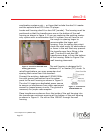
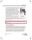
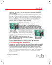
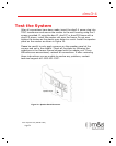
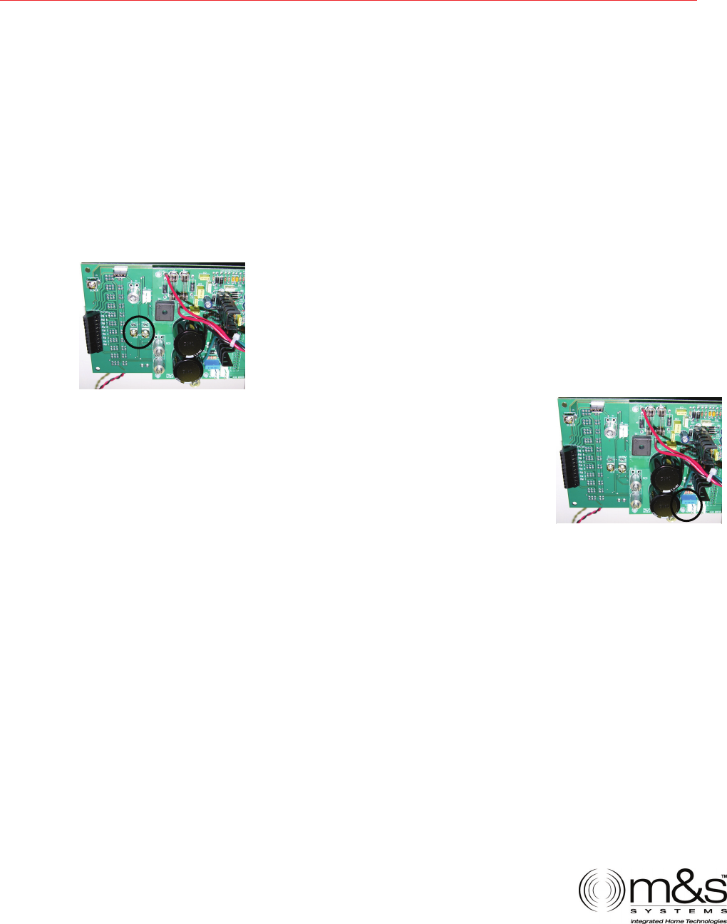
Figure 15 - Door
Station Connections
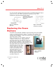
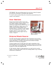
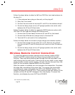
Figure 16 – Chime
Plug Connection
marked on the inside of the door access panel on the left side of the
dmc3-4 master.
Connect the green wire(s) from the patio station(s) to the Patio green
terminal. Connect the patio Black wire(s) to the patio Black terminal.
Note: Only two patio stations can be connected to the patio terminals.
Connect the Red wire with the other Red wires to the Red terminal.
Connect the White wire with the other White wires to the White
terminal. Refer to Figure 14 for wire placement.
Connect the red and black wires of the door station cables
(MS4DCX/MS4DCXSC) to the red and black door
speaker terminals on the dmc3-4 master as
shown in Figure 15. When using MS4DCXSC
shielded wire, insulate the bare wires using some
of the jacket material to prevent shorting to the
circuit board. Connect this wire to terminal labeled
shield. Connect all orange wires
from the door stations to the
common terminal on the MC3 or
MC8. Connect each yellow wire to a note selection
terminal. (Do not connect more than one yellow wire
per note terminal.)
Plug in the modular chime plug to the 4 pin
connector labeled as CHIME on the dmc3-4 master
unit as shown in Figure 16.
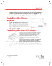
Connect the optional dmc1CD player RCA cables and control wire.
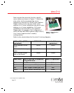
Connecting the Antenna
Separate the intercom cables from the antenna leads, if grouped together
the intercom cables can shield the antenna leads resulting in poor radio
reception. Keep the antenna leads away from metal ductwork and
aluminum backed insulation. These can also shield the antenna leads.
The number and style of antenna leads will vary based on the intercom
system being replaced. The dmc3-4 system is designed to use the
existing antenna.
$QEG$QEG 1.1.