íúóáéÚÍÓÁ
11
B. WALL MOUNTING (No Standard Wall Jack)
1. Drill two holes with a vertical distance between the two marked
positions of 3
15/16
" (100 mm) as shown in Figure 6.
2. Drive a screw into each of the holes. Tighten them to the end
of the screw line, only leaving the smooth part of the screw head
outside the wall.
3. Hang the unit onto the screws, then slide it down firmly to
fasten the base securely.
BELT CLIP INSTRUCTION
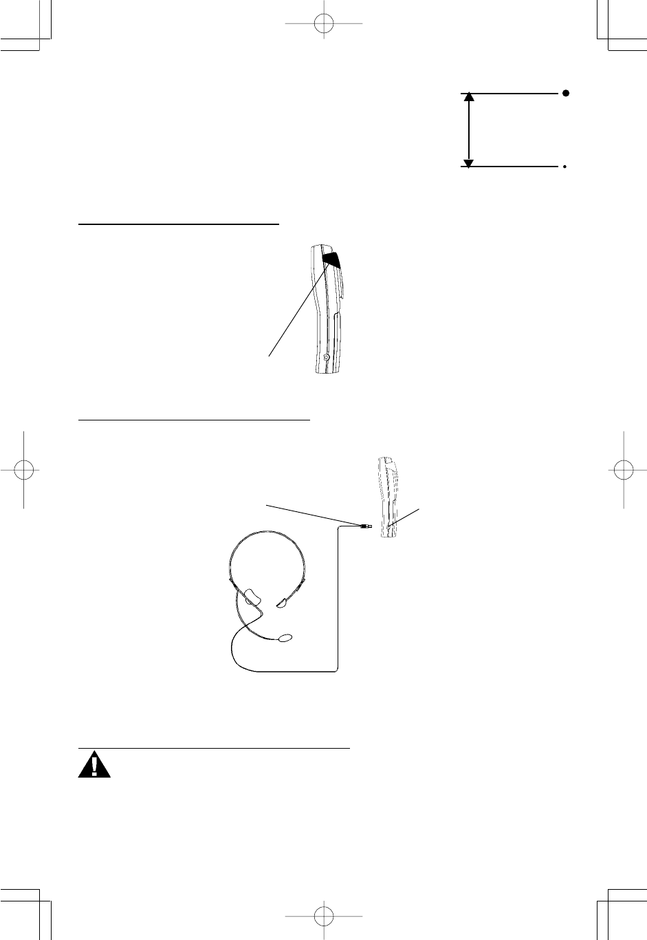
Clamp the belt clip at the back of the handset as shown in Figure 7.
(Figure 7)
Belt Clip
(Figure 8)
Press the TALK button to answer or place a call using the headset. Refer to the manufacturer's
headset manual for more details.
BASE UNIT POWER CONNECTION
CAUTION:
You must use a Class 2 Power Source 9VAC 500mA. The plug must correctly fit the unit's
adapter jack.
1. Plug the adapter into a standard AC outlet.
2. Insert the small plug into the adapter jack on the rear of the base as shown in Figure 9.
CONNECTING THE HEADSET
For hands free conversation, a headset (not included) is connected to the headset jack as
shown in Figure 8. The handset receiver and microphone are disabled when the headset is
connected.
Headset
Jack
Headset Plug (2.5mm)
3
15/16
”
(100 mm)
(Figure 6)
MPH7895/04281A(English).put 7/5/01, 4:07 PMPage 12 Adobe PageMaker 6.5C/PPC


