


6
Overview
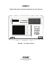
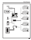
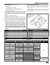
The VMC1 System
Designed for installation in new homes, the VMC1 is a Whole
House Color Video Security Intercom system that provides
room to room communication, multiple camera support,
basic home automation controls, and video security for mid to
large residential applications. VMC1 provide years of service
and security for the homeowner as many people move into
‘smart home’ environment. New housing takes advantage of
state of the art electronics, internet, and security applications
such as video surveillance and monitoring. VMC1 provides up
to 20 remote intercom stations, three video camera stations,
and offers music and communication for the whole house.
With multiple 12 volt Control Outputs, VMC1 can trigger
lights, monitors, voice and text message alerts, and e-mail
door chime alerts delivered to a smart phone. VMC1 offers a
wide range of capacities with expanded options, accessories,
and recommended parts. (See Appendix A).
It is important that each step of the installation be
carefully completed by the installer. In the event you need
troubleshooting assistance, please call our technical support
staff at 1-800-421-1587.
General Information
The following general procedures must be observed in
relation to the location and installation of VMC1 components:
Where stations are to be installed outdoors, appropriate
measures to provide protection from the weather are to be
taken.
The power supply should be located in an area with suffi cient
space for heat dissipation.
Guidelines for maximum cable lengths as set out in this
manual are to be observed to avoid the possibility of operating
problems due to excessive cable voltage drop.
Interference
The circuitry of the intercom is designed to minimize the
effects of Radio Frequency Interference (RFI); and there will
be minimal and occasional radio frequency interference as
power outages, lightning storms, and any electrical apparatus
can affect the system. To reduce instances of interference,
reduce any unwanted audible buzz in audio appliances
such as microphone amplifi er, speaker amplifi er, car radio,
telephones etc, you add on-board EMI fi lters or special layout
techniques to help bypass EMI or improving RF immunity.
Most circuits have integrated RF fi lters or special design that
prevents demodulation of high-frequency carriers. The use of
microwaves, cell phones, cable television, bug zappers, even
heating pads in close proximity, can create interference.
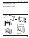
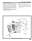
Master Station
The Master Station should be positioned at a suggested
height of 4-1/2’ to 5-1/2’ from the fl oor to the center of the
unit. As all wiring from other stations is generally terminated
at the rear of the Master Station, the wall should be no less
than 3 inches in depth. Use the VMC1MB to provide adequate
support for the unit.
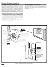
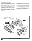
Room Stations
To avoid audio feedback, Room Stations should be kept at least
10 feet away from other stations. Never have more than one
station in any one room and avoid mounting stations in the
same wall cavity (i.e. directly below and above one another in
a two-story house). A suitable height is generally 4.5 feet from
the fl oor to the center of the unit. For Room Stations mounted
on wood frame walls, place near a stud to allow for adequate
support. For tiled surfaces, install a wall box before lining or
tiling the walls. Cut the tiles to the inside dimensions of the
wall box. Where Room Stations are mounted outside and are
exposed to the weather, the fi tting of weatherproof covers is
recommended (p/n DSWS). Stations must not be installed in
saunas.
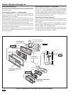
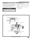
Door Stations
Door Stations are best located adjacent to the front door
or at the front gate at a suggested height of 4’-6” and may
require a wall box depending upon the surface to which they
are to be affi xed. Door Stations are weather resistant, but
should not be exposed directly to rain or extreme weather.
Any station exposed to the weather requires a weather shield.
When equipped with the appropriate weather shield the Door
Station is designed to meet ANSI/IEC 60529 IP31 weather
proof standards.
Gates and Entrances
Where stations are to be installed in brick or concrete columns
at a front gate, the cable should be run in conduit from the
station to below ground level and back to the house.
Cameras
For Door Stations fi tted with cameras, consideration must be
given to the viewing area of the camera taking factors such as
lighting and sun exposure into account.
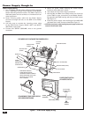
Power Supply
The Power Supply should be attached to the VMC1MB as
directed. Improper installation of the Power Supply can lead
to unit malfunction and void the warranty. The Power Supply
needs suffi cient space to dissipate heat effectively.
AM & FM Antennas
The antenna arrangement is critical to the installation for quality
radio reception. Place AM and FM antennas at the highest
point of the roof and at least 6 feet away from any electrical
or intercom wiring. Both AM and FM antennas are directional,
and correct positioning requires some experimentation to
achieve the best possible result. Antenna wires should also
be positioned at the highest and most accessible point in
the roof. Allow additional cable at the mounting bracket for
termination, at least 3 feet for the Master Station.