


15
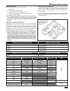
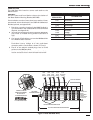
Data Hub Wiring
TIA-568A WIRING STANDARD
DATA HUB RJ-45
MODULAR PLUG
Cat-5 WIRE COLOR
Pin 1 White/Green
Pin 2 Green
Pin 3 White/Orange
Pin 4 Blue
Pin 5 White/Blue
Pin 6 Orange
Pin 7 White/Brown
Pin 8 Brown
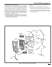
Figure 8. H628 Data Hub Wiring
H628 Data Hub
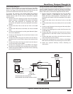
The H628 Data Hub is used to connect each station to the
Master Station.
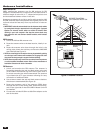
Pull Wires
Pull all the Door and Room Station cables to the location of
the Master Station Mounting Bracket (VMC1MB).
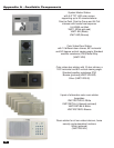
If the installation consists of more than 5 room stations, Linear
recommends using the optional Linear DMD-16 (16 stations)
Data Distribution module and the Model H275 Universal
Bracket (Optional, see Appendix A).
1. Determine a mounting location for the H628 Data Hub. It
is recommended to use a Model H275 Universal Bracket
(Optional, see Appendix A).
2. Terminate Cat-5 cables from stations with RJ-45 modular
plugs wired to TIA-568A wiring standard (See Table at
right).
3. Cut a length of Cat-5 cable to run from the H628 Data Hub
to the Master Station location.
4. Strip back about 8” of cable insulation and use a 110
Punch-down tool to bridge all of the punch-down
connectors with the Cat-5 cable as shown in Figure 8.
5. Plug all of the station’s modular plugs into the RJ-45
sockets on the H628 Data Hub.
6. Route the bridged Cat-5 cable to the Master Station
location and secure it so it won’t fall back into the wall.
1 BROWN
2 WHITE/BROWN
3 GREEN
4 WHITE/GREEN
5 ORANGE
7 BLUE
6 WHITE/ORANGE
8 WHITE/BLUE
CAT-5 CABLE
TO MASTER STATION
FROM
DOOR
STATION
FROM
ROOM
STATION
FROM
ROOM
STATION
FROM
ROOM
STATION
FROM
NIGHTSTAND
STATION
110 PUNCHDOWN CONNECTORS
110 PUNCH-DOWN TOOL
CAREFULLY PUNCH
WIRES INTO TERMINAL
BLOCK USING A
110 PUNCH-DOWN TOOL
RJ-45 PLUG SOCKETS
8” OF CAT-5 CABLE INSULATION STRIPPED