


16
Antenna Installation
Radio Antennas
VMC1 requires two antennas, one for AM and one for FM
reception. The AM antenna is a 25-foot wire the FM antenna is
a 25-foot length of coax with a “T” shaped wire dipole at one
end that attaches between rafters in the attic.
Antenna arrangement is crucial to quality radio reception. AM
and FM antennas should be placed at the highest point of the
roof and at least six feet away from any electrical or intercom
wiring.
✓ IMPORTANT! Isolate the antenna leads from the intercom station cables
by running them through a separate hole in the ceiling plate. If grouped
together, the intercom station cables can shield the antenna leads
resulting in poor radio reception. Also keep the antenna leads away
from metal duct work and aluminum backed insulation, which reduces
reception.
AM Antenna
1. Unroll the 25-foot AM antenna wire.
2. Route the antenna wire to the best location, ideally in an
attic.
3. Route the antenna wire down through the hole in the
ceiling plate, down the stud bay to where the VMC1MB
was installed (see Figure 9).
✓ NOTE: the overall length of the antenna wire may be extended by splicing
on to the ‘open’ end of antenna with insulated wire. The gauge end of the
wire should be strong enough to support it without breaking.
✓ NOTE: Some customers may want to use an external tuned loop antenna
or vertical amplifi ed broadband antenna. Refer to those manufacturer’s
installation instructions for further information.
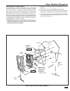
FM Antenna
1. Unroll and examine the FM antenna. The antenna is
formed by spreading the red and black wires at the end
of the COAX. The terminal lug at the end of each wire is
for screw mounting the wires outstretched. The antenna
is provided with an F type connector allowing for easy
connection of additional cable.
2. Use screws to attach the red and black antenna leads to
the structure outstretched (See Figure 9).
3. Route the connector end of the antenna COAX down
through the hole in the ceiling plate, down the stud bay,
and on the right side of where the VMC1 Master Unit will
be installed.
4. Connect the included 75 Ohm to 300 Ohm adapter to the
end of the cable.
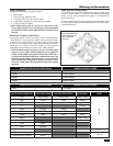
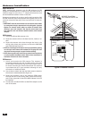
Figure 9. Antenna Location
FM ANTENNA
WIRING
75 OHM TO 300 OHM
ADAPTER
AM ANTENNA
WIRING
MASTER STATION
ATTIC
ORIENTATE FM ANTENNA
FOR STRONGEST RECEPTION
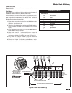
POWER BANDMEM
ALARM DOWNUP
12
34
5
5ME-UP
+
TUNER
AUX MUSIC
RADIO FILTER
GATE STATUS
AUX OUTPUT 1
AUX OUTPUT 2
-
+
VOLUME
AUX 1
AUX 2
INPUTFILTER
VID 1
VID 2
VID 3
LOCK
PRIVMON
MUS
CLEAR
HOUSE
DOOR
AUX
3
4
5
6 7
1
2