


14
Power Supply Rough-In
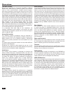
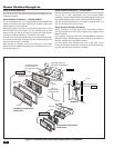
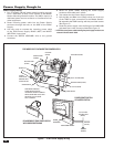
Figure 7 - TE6D Power Supply Wiring
Power Supply Wiring
1. Run a 14 AWG 120 VAC power cable (including ground)
from a dedicated 15-amp circuit breaker to the Master
Station Mounting Bracket location. The VMC1 requires a
dedicated power source so there’s no interference from
other equipment.
2. Route incoming power cable into the Power Supply
enclosure through the hole on the SIDE of the Power
Supply.
3. Use wire nuts to connect the incoming power cable
to the TE6D Power Supply BLACK (HOT) and WHITE
(NEUTRAL) input wires.
4. Connect the GREEN (GROUND) wire to the ground
conductor.
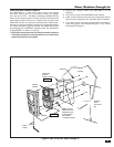
5. Secure all power cables entering the Power Supply
enclosure with cable strain reliefs.
6. Tuck cables into the Power Supply enclosure.
7. Pull the Red and Black low voltage wires out of the top
of the TE6D for later connection to the Master Station.
Re-assemble the TE6D housing with the provided screws
(See Figure 7).
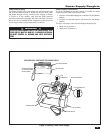
8. Hook the power supply onto the fl ange of the VMC1MB
and attach the it with screw provided (See Figure 7).
✓ NOTE: Be sure all power cables entering the power supply enclosure are
secured with cable strain reliefs.
GROUND WIRE
(GREEN)
NEUTRAL WIRE
(WHITE)
HOT WIRE
(BLACK)
INSERT
WIRE FROM
BREAKER INTO
STRAIN RELIEF
WIRE NUTS
PRE-WIRED SELF CONTAINED TE6D POWER SUPPLY
FEED WIRES THROUGH
STRAIN RELIEFS ON TOP
HOUSING AS SHOWN. CONNECT
WIRES USING WIRE NUTS, THEN
RE-INSTALL TOP HOUSING
WITH 4 SCREWS
STRAIN RELIEF
STRAIN RELIEF
TOP HOUSING
BOTTOM HOUSING
PLUS 13V WIRE (RED)
NEGATIVE WIRE (BLACK)
RE-ASSEMBLED TE6D POWER SUPPLY
WITH WIRES PROTRUDING
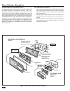
TE6D POWER SUPPLY
SCREW
(PROVIDED)
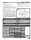
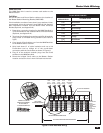
NEUTRAL
(WHITE)
GROUND
(GREEN)
110/120V HIGH
VOLTAGE INPUT
(BLACK)
POWER IDENTIFICATION
AT MASTER STATION
PLUS 13V
WIRE (RED)
NEGATIVE
WIRE (BLACK))