


17
Auxiliary Output Rough-In
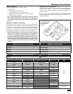
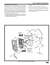
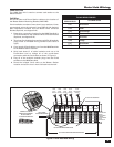
Figure 10. Electric Door Strike Wiring
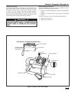
Chime Activated Control Output Rough-In
The Chime Activated Control Output allows for any number of
security related automation functions including 10 available
door chimes. To connect an auxiliary Chime refer to Figure 10.
Refer to the hook-up instructions supplied with the chime.
1. Route a blue and a black 18 gauge wire from the Door
Station location or VMC1VDS to the optional 12V
Model 284 relay. (See Appendix). Following this color
convention will assist in the fi nal installation of the Door
Station.
2. Connect the blue wire to the red coil wire on the 284
relay.
3. Connect the black wire to the white coil wire on the 284
relay.
4. Connect a red 18 gauge wire to the green Normally Open
wire on the 284 relay.
5. Connect a red 18 gauge wire to the blue Common wire
on the 284 relay.
6. Connect the other end of the red wire from the relay to
the Yellow wire on the RT35 or either of the wires on the
RT11.
7. Connect the other end of the red wire from the relay to
one of the wires from the Chime.
8. Connect the remaining wire on the Chime to the Yellow/
Red wire on the RT35 or the remaining wire on the RT11.
9. Install the optional Auxiliary Chime following its
instructions.
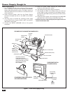
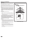
Door Release Rough-in
The Door Release Trigger can be activated from the VMC1
Master or any remote room station by pressing the Lock
button. The Trigger will deactivate after 4 seconds and can be
activated multiple times while the intercom is active.
To connect the optional Linear Model DRW Door Release
Mechanism, refer to Figure 10 For controlling other door
release devices, refer to the hook-up instructions supplied
with the device.
1. Route a blue and a white 18 gauge wire from the Door
Station location or VMC1MB to the optional 12V Model
284 relay. (See Appendix A). Following this color
convention will assist in the fi nal installation of the Door
Station.
2. Connect the blue wire to the red coil wire on the 284
relay.
3. Connect the white wire to the white coil wire on the 284
relay.
4. Connect a red 18 gauge wire to the green Normally Open
wire on the 284 relay.
5. Connect a red 18 gauge wire to the blue Common wire
on the 284 relay.
6. Connect the other end of the red wire from the relay to
the Yellow wire on the RT35 or either of the wires on the
RT11.
7. Connect the other end of the red wire from the relay to
one of the wires from the DRW.
8. Connect the remaining wire on the DRW to the Yellow/
Red wire on the RT35 or the remaining wire on the RT11.
9. Install the optional DRW into the door frame following
the included instructions.
GRAY
N/C NORMALLY CLOSED
COMMON
GREEN
NORMALLY OPEN
MODEL DRW
ELECTRONIC DOOR STRIKE
OR CHIME
BLUE
24VAC
110VAC
MODEL RT11 OR RT35
PLUG-IN TRANSFORMER
DOOR
STATION
MODEL 284
12V 5 AMP RELAY
BLUE
WHITE
RED
WHITE
BLACK
USE WHITE WIRE FOR DOOR RELEASE
USE BLACK WIRE FOR AUXILIARY CONTROL OUTPUT
VMC1VDS
DRW