


Contents
v
Power and Hardware Connectors ......................................................................72
Add-In Board and Peripheral Interface Connectors............................................73
Front Panel Connectors..............................................................................................74
Desktop Board Resources...................................................................................................75
Memory Map ..............................................................................................................75
DMA Channels ...........................................................................................................75
I/O Map ......................................................................................................................76
Interrupts....................................................................................................................78
A Error Messages and Indicators
BIOS Beep Codes...............................................................................................................79
Enhanced Diagnostic LEDs.................................................................................................80
BIOS Error Messages .........................................................................................................82
B Regulatory and Integration Information
Regulatory Compliance .......................................................................................................85
Product Certification Markings.............................................................................................86
Installation Precautions .......................................................................................................86
Installation Instructions........................................................................................................87
Ensure Electromagnetic Compatibility (EMC) .............................................................87
Ensure Chassis and Accessory Module Certifications ................................................87
Prevent Power Supply Overload.................................................................................88
Place Battery Marking on the Computer.....................................................................88
Use Only for Intended Applications.............................................................................88
Figures
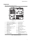
1. Desktop Board Components.......................................................................................... 9
2. Location of Standby Power Indicator.............................................................................19
3. AGP Card with Retention Notch....................................................................................22
4. Installing the AGP Card Retention Mechanism .............................................................23
5. Removing the AGP Card ..............................................................................................24
6. Removing the AGP Card Retention Mechanism ...........................................................25
7. Installing the D850GB I/O Shield ..................................................................................26
8. Installing the D850GBAL I/O Shield ..............................................................................26
9. Location of the Mounting Screw Holes..........................................................................27
10. Location of the Processor RM Mounting Holes .............................................................28
11. Installing the Processor RM..........................................................................................29
12. Installing a Processor....................................................................................................30
13. Applying Thermal Grease to the Processor Surface .....................................................31
14. Attaching the Fan Heatsink Clip....................................................................................31
15. Installing the Heatsink Clips..........................................................................................32
16. Connecting the Processor Fan Cable to the Processor Fan Connector ........................33
17. Installing a Memory Module..........................................................................................35
18. Removing the Battery ...................................................................................................37
19. Connecting the IDE Cable.............................................................................................38
20. Location of the BIOS Configuration and USB Port 2 Routing Jumpers .........................39
21. Connector Groups ........................................................................................................69
22. Back Panel Connectors ................................................................................................70