


Desktop Board Features
19
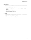
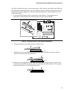
If the system has a dual-colored power LED on the front panel, the sleep state is indicated by the
LED turning amber.
OM10442
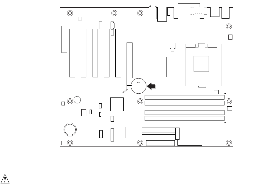
CR6F1
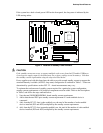
Figure 2. Location of Standby Power Indicator
CAUTION
If the standby current necessary to support multiple wake events from the PCI and/or USB buses
exceeds power supply capacity, the board may lose register settings stored in memory. Calculate
the standby current requirements using the steps described below.
Power supplies used with this board must be able to provide enough standby current to support the
standard Instantly Available (ACPI S3 sleep state) configuration as outlined in Table 3. Values are
determined by specifications such as PCI 2.2. Actual measurements may vary.
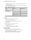
To estimate the total amount of standby current required for a particular system configuration,
standby current requirements of all installed components must be added. Refer to the descriptions
in Table 3 and follow the steps outlined below:
1. Note the total D850GB/D850GBAL board standby current requirement.
2. Add to that the total PS/2 port standby current requirement if a wake-enabled device is
connected.
3. Add, from the PCI 2.2 slots (wake-enabled) row, the total of the number of wake-enabled
devices installed (PCI and AGP) multiplied by the standby current requirement.
4. Add, from the PCI 2.2 slots (nonwake-enabled) row, the total of the number of wake-enabled
devices installed (PCI and AGP) multiplied by the standby current requirement.