


Intel Desktop Board D850GB/D850GBAL Product Guide
34
Installing and Removing Memory
CAUTIONS
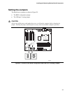
Before installing or removing RIMM modules, make sure that AC power has been removed by
unplugging the power cord from the computer. The standby power indicator LED should not be lit
(see Figure 2 on page 19) for the location of the standby power indicator LED location). Failure
to do so could damage the memory and the board.
The board supports combinations of no more than 32 RDRAM components per RDRAM channel.
If the total number of RDRAM components installed in all RIMM sockets exceeds 64, the computer
will not boot.
A Continuity RIMM (CRIMM) module must be installed in any unused memory connector or the
board will not boot.
Incorrect insertion of a RIMM module or a CRIMM module in a RIMM connector can damage the
D850GB/D850GBAL board.
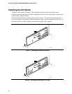
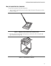
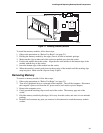
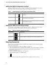
Installing Memory
The board’s memory module consists of four sockets arranged as bank 0 and bank 1. The pair of
sockets closest to the processor is for bank 0, as shown in Figure 17. The memory module
requirements are listed in the Main Memory section on page 11.
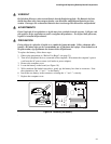
When adding memory:
• Install a pair of RIMMs in the sockets in bank 0 first. The RIMMs must be identical in speed,
size, and density.
• If desired memory configuration has been achieved in bank 0, install CRIMMs in the sockets
in bank 1.
• If memory is to be installed in bank 1, the RIMM modules to be installed must be identical in
size and density to each other, and match the speed of the RIMM modules in bank 0. The
RIMM modules do not, however, need to match those in bank 0 in size and density. For
example, if bank 0 has two 128 MB RIMMs of PC800 RDRAM, bank 1 would require PC800
RDRAM also, however, any other supported RIMM modules such as 64 MB or 192 MB could
be used.
• The BIOS detects the size and type of installed memory.