


Installing and Replacing Desktop Board Components
23
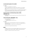
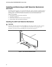
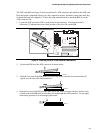
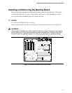
The AGP card RM (see Figure 4) encloses the board’s AGP connector and stabilizes the AGP card.
Place the board (component side up) on a flat, supportive surface, preferably on the anti-static bag
in which the board was shipped in. Follow the steps outlined below to attach the RM (A) to the
AGP connector (B):
1. Locate the AGP connector (J5E1) on the board as shown below. Note that the board’s
silkscreen (C) indicates the correct final position of the lever (D) on the RM.
OM10630
B
A
C
D
E
Figure 4. Installing the AGP Card Retention Mechanism
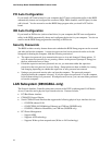
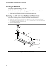
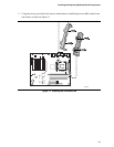
2. Position the RM over the AGP connector as shown below.
OM10111
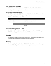
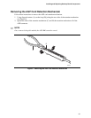
3. Push the lever end of the RM in the direction of the arrow until the two rearmost tabs (E)
spread over the end of the AGP connector.
OM10180
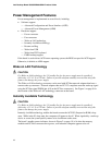
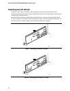
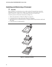
4. Push the free end of the RM over the other end of the AGP connector and press down evenly
on both ends of the RM until all four tabs click underneath the AGP connector. Do not apply
unnecessary pressure to avoid damaging the board.
OM10181