


68
12
CONTROL COMMAND
1
2
3
4
5
6
7
8
9
10
11
12
13
14
15
16
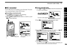
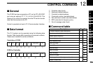
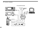
■ General
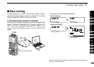
The IC-R20 can be connected to a PC via the PC’s RS-232C
port using an optional CT-17
CI-V LEVEL CONVERTOR
. This
allows you to control the receiver from the PC and/or transfer
data from the receiver to the PC.
Control is provided via Icom’s CI-V Communication Interface.
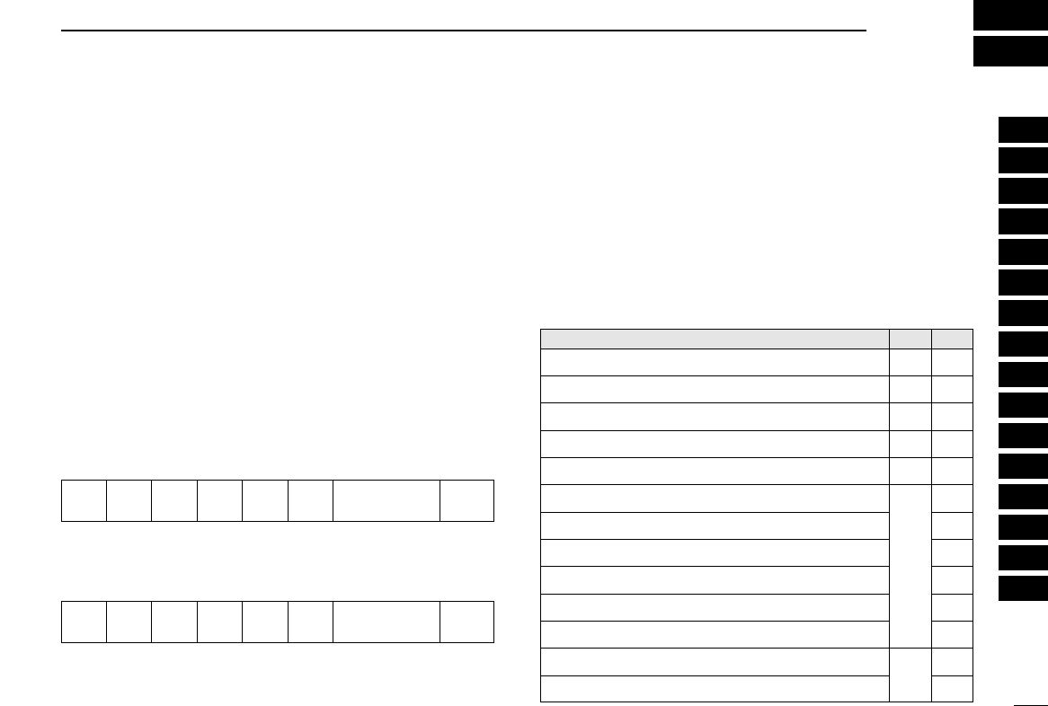
■ Data format
The CI-V system can be operated using the following data
formats. Data formats differ according to command numbers.
A data area is added for some commands.
Controller ➡ IC-R20
IC-R20 ➡ Controller
q Preamble code (fixed)
w Receiver’s default address
e Controller’s default address
r Command number (see table below)
t Sub command number (see table below)
y BCD code data for frequency entry
u End of message code (fixed)
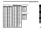
■ Command table
FE FE 6C E0 Cn Sc Data area FD
q wert y u
FE
FE E0 6C Cn Sc Data area FD
q ewrt y u
Description Cn Sc
Transfers frequency data (transceive) 00 —
Transfers mode data (transceive) 01 —
Reads display frequency 03 —
Reads display mode 04 —
Sets frequency data 05 —
Sets LSB mode
06
00
Sets USB mode 01
Sets AM mode 02
Sets CW mode 03
Sets FM mode 05
Sets WFM mode
06
Reads squelch condition (open or closed)
15
01
Reads S-meter level
02