12 - 5
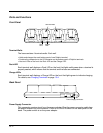
Back Panel
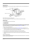
Latch
The latch sits on top of the spring arm assembly and holds the back of the terminal securely in
place. The 9950/9951 version of the base contains a special latch to accommodate the
integrated pistol-grip handle.
Locking Tabs
When positioned as shown in the above graphic, the locking tabs secure the spring arm
assembly, latch, and terminal in place. When seating a terminal, turn both arms up to allow the
spring arm to move as necessary while the terminal is being inserted. After the terminal is
seated, turn both arms toward the center to lock them.
Both locking tabs must be pointing up to insert or remove a terminal in the base.
Spring Arm Assembly
The spring arm assembly is the column that connects the latch to the back of the base.
Ball Joints
There are two ball joints: one on the back of the base and one on the mounting bracket. Both
ball joints are inserted into the bracket and secured to mount the base.
Connectors
The power and RS-232 connectors are located on the bottom panel.
For more information, see Bottom Panel on page 12-3.
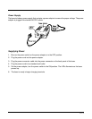
Brackets
Bracket
The bracket contains the turnscrew and two slots. Ball joints are inserted into each slot and
secured with the turnscrew.
Turnscrew
The turnscrew is located on the top of the bracket. Rotate the turnscrew to secure or loosen
the ball joint slots.
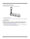
Mounting Bracket
The mounting bracket is what you attach to the mounting surface. It is comprised of a ball joint
and flat disk. The disk contains drill holes you use to secure the base to the mounting surface.
Power
Note: Honeywell recommends that you leave the base connected to its power source at all times.
The base is powered via the power connector on the bottom panel; see Bottom Panel on page 12-3. Both
the power and serial connectors are straight out, not at an angle. The base must be powered by a 12 to
48 volt DC source.


