


WA
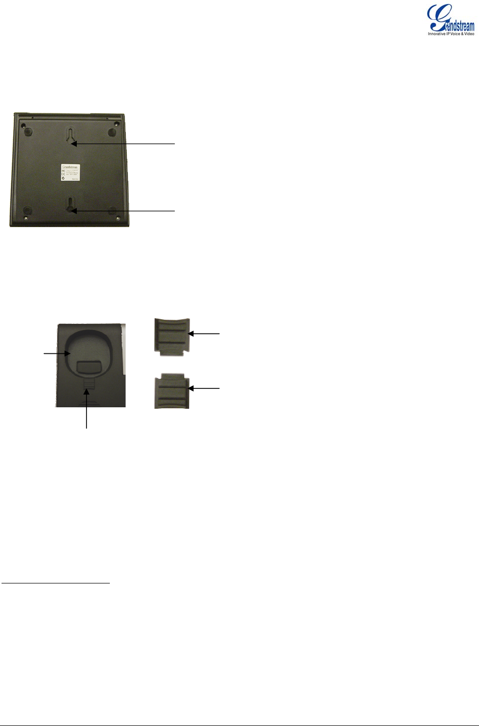
GX all m one on the wall, place two fixed hangers on the wall,
ang the back of the phone on the fixed hangers.
om the handset cradle, rotate the tab and plug it
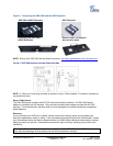
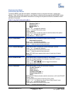
additional programmable extensions.
n has 56 multi-purpose keys, dual color LEDs (red/green) and support BLF (busy
ld) and BLA (bridg d line appearance). Connect the first GXP -EXT to the GXP-2000 using the
e. The first GXP-Ext draws power directly from the phone.
red,
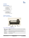
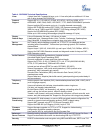
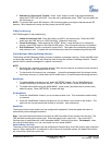
LL MOUNT
P-2000 can be w
ounted. To position the ph
h
Top Wall
Mount hole
Bottom Wall
Mount hole
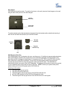
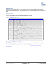
To use the handset, pull out the tab (extension downward) fr
back into the slot with the extension up to hold the handset.
Tab with
Handset
Rest
extension
Tab with
extension up
GXP
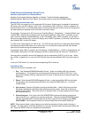
EXTENSION SIDE CAR
GXP-2000 supports two (2) extension side cars, providing up to 112
Tab
Each GXP Extensio
la
mp fie e
PS2 cable found in the GXP Ext packag
Connect the second GXP Ext using the connection plate and the PS2 cable. The GXP2000 will
automatically reboot and power up the GXP Extensions. Grandstream recommends, though not requi
to use a separate power supply with the second GXP Ext. NOTE: should your system loose power,
please unplug your devices and power up the GXP-2000 first.
Powering up the system:
1. The GXP-2000 will boot up first;
2. The GXP LEDs will be solid red;
3. The status light in t
4. All of the LED indic
he top right corner of the GXP-Ext will blink red;
ators on the GXP-Ext will flash three times;
ner of the GXP-Ext will turn to solid green.
5. The status light at the top right cor
Grandstream Networks, Inc. GXP-2000 Users Manual Page 6 of 33
Firmware 1.1.1.14 Last Updated: 12/2006