


14
Section IV Operation (Continued)
Thus when a voice is used in place of a whistle or tone, in the proper listening
mode the voice will be received correctly whereas in the incorrect mode, the
voice will be translated backwards and cannot be made intelligible by the voice
lock control. When listening to an AM transmission, a correct sideband is heard in
either mode since both upper and lower sideband are received.
Once the desired SSB mode has been selected, frequency adjustment may be nec-
essary in order to make the incoming signal intelligible, the VOICE LOCK control
allows the operator to vary frequency above and below the exact-center frequency
of the received signal. If the sound of the incoming signal is high or low pitched,
adjust the operation of the VOICE LOCK. Consider it as performing the same func-
tion as a phonograph speed control. When the speed is set too high, voices will be
high-pitched and if set too low, voices will be low-pitched. Also, there is only one
correct speed that will make a particular record produce the same sound that was
recorded. If the record is played on a turntable that rotates in the wrong direction
(opposite sideband) no amount of speed control (VOICE LOCK) will produce an
intelligible sound.
An AM signal received while listening in one of the SSB modes will produce a
steady tone (carrier) in addition to the intelligence, unless the SSB receiver is tuned
to exactly the same frequency by the VOICE LOCK control. For simplicity it is rec-
ommended that the AM modes be used to listen to AM signals.
15
Section IV Operation (Continued)
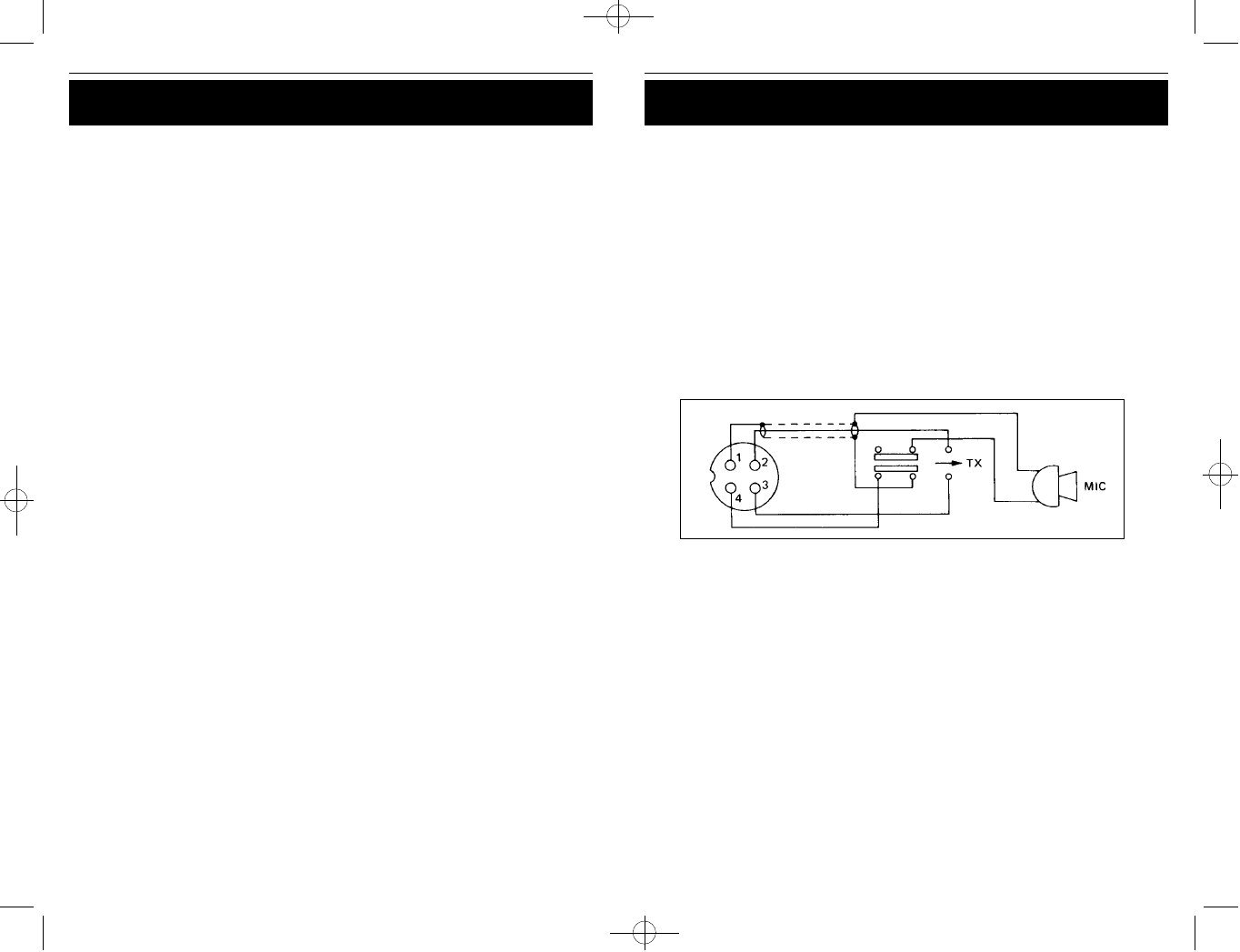
ALTERNATE MICROPHONES AND INSTALLATION
For best results, the user should select a low-impedance dynamic type micro-
phone or a transistorized microphone. Transistorized type microphones have a low
output impedance characteristic. The microphones must be provided with a 4-lead
cable. The audio conductor and its shielded lead comprise two of the leads. The
third lead is for receive control, the forth is for transmit control.
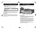
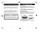
The microphone should provide the functions shown in schematic below.
4 WIRE MIC CABLE
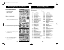
Pin Number Mic Cable Lead
1 Grounding
2 Audio Lead
3 Transmit Control
4 Receive Control
Fig. 1. Cobra 148 GTL ST microphone schematic.
If the microphone to be used is provided with pre-cut leads, they must be revised
as follows.
1. Cut leads so that they extend 7/16” beyond the plastic insulating jacket of the
microphone cable (see Fig. 2.)
2. All leads should be cut to the same length. Strip the ends of each wire 1/8”
and tin the exposed wire.
Before beginning the actual wiring, read carefully, the circuit and wiring informa-
tion provided with the microphone you select. Use the minimum head required in
soldering the connections. Keep the exposed wire lengths to a minimum to avoid
shorting when the microphone plug is reassembled.
148.GTL.ST.MANUAL 10/1/98 10:56 AM Page 17