


6
Section III Installation
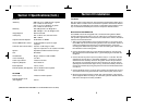
IGNITION NOISE INTERFERENCE
Use of a mobile receiver at low signal levels is normally limited by the presence
of electrical noise. The primary source of noise in automobile installations is from
the generator and ignition system in the vehicle. Under most operating conditions,
when signal level is adequate, the background noise does not present a serious
problem. Also, when extremely low level signals are being received, the transceiv-
er may be operated with vehicle engine turned off. The unit requires very little
current and therefore will not significantly discharge the vehicle battery.
Even though the COBRA 148 GTL ST has ANL and NB controls, in some installa-
tions ignition interference may be high enough to make good communications
impossible. The electrical noise may come from several sources. Many possibilities
exist and variations between vehicles require different solutions to reduce the
noise. Consult your COBRA dealer or a 2-way radio technician for help in locat-
ing and correcting the source of severe noise.
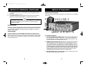
ANTENNA
Since the maximum allowable power output of the transmitter is limited by the
FCC, the antenna is one important factor affecting transmission distance. Only a
properly matched antenna system will allow maximum power transfer from the 50
ohm transmission line to the radiating element. In mobile installations (cars,
trucks, boats, etc.), an antenna system that is non-directional should be used.
A vertically polarized, quarter-wavelength whip antenna provides the most reliable
operation and greatest range. Shorter, loaded-type whip antennas are more attrac-
tive, compact and adequate for applications where the maximum possible dis-
tance is not required. Also, the loaded whips do not present the problems of
height imposed by a full quarter-wavelength whip.
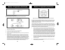
Mobile whip antennas utilize the metal body of the vehicle as a ground plane.
When mounted at a corner of the vehicle they are slightly directional, in the
direction of the body of the vehicle. For all practical purposes, however, the radia-
tion pattern is nondirectional. The slight directional characteristic will be observed
only at extreme distances. A standard antenna connector (type SO239) is provided
on the transceiver for easy connection to a standard PL 259 cable termination.
If the transceiver is not mounted on a metal surface, it is necessary to run a sepa-
rate ground wire from the unit to a good metal electrical ground in the vehicle.
When installed in a boat, the transceiver will not operate at maximum efficiency
without a ground plate, unless the vessel has a steel hull.
Before installing the transceiver in a boat, consult your dealer for information re-
garding an adequate grounding system and prevention of electrolysis between fit-
tings in the hull and water.
7
Section III Installation (Continued)
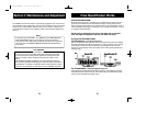
TUNING THE ANTENNA FOR OPTIMUM SWR
Since there is such a wide variety of base and mobile antennas, this section will
strictly concern itself to the various types of mobile adjustable antennas.
Because antenna length is directly related to the channel frequency, it must be
tuned to resonate optimally all 40 channels of the transceiver. Channel 1 requires
a longer antenna than Channel 40 because it is a lower frequency.
Due to the various methods of adjusting antennas for proper SWR we have chosen
what we think is the optimum method:
A. Antennas with adjustable screws (set screws).
1. Start with the antenna extended and tighten the set screw lightly enough so
that the antenna can be lightly tapped with your finger for easy adjustment.
2. Set your COBRA 148 GTL ST to Channel 21. Press the PTT (Push-to-Talk)
switch, and tap the antenna (making it shorter). The SWR meter will show a
lower reading each time the antenna is tapped. By continuing to shorten the
antenna you will notice the SWR reading will reach a low point and then
start rising again. This means that you have passed the optimum point for
Channel 21. Extend the antenna a short distance and again follow the
procedure above.
When the lowest point has been reached, switch to Channel 1 and then to
Channel 40 and compare SWR readings. They should be almost equal.
B. Antennas which must be cut to proper length.
1. Follow the same procedure as above, but adjust the length by cutting in 1/8”
increments until a good match is obtained.
2. Be very careful not to cut too much at one time, as once it is cut, it can no
longer be lengthed.
3. The whip is easily cut by filing a notch all the way around and breaking the
piece off with a pliers.
NOTE
THE PROPER SETTING IS ACHIEVED WHEN THE SWR IS
1.5 OR BELOW, AND WHEN IT HAS THE SAME READING
FOR CHANNELS 1 AND 40.
If you are having difficulties in adjusting your antenna, check the following:
A. All doors must be closed when adjusting the antenna.
B. Make sure the antenna base is grounded.
C. C h e c k your coaxial cable routing (it may be pinched when routed into the car).
148.GTL.ST.MANUAL 10/1/98 10:56 AM Page 9