


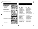
Section II Specifications (Cont.)
4
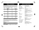
RECEIVER
Sensitivity SSB: 0.25 µV for 10dB (S+N)/N at greater
than 1/2-watt of audio output.
AM: 0.5 µV for 10 dB (S+N)/ at greater
than 1/2-watt of audio output.
Selectivity AM: 6dB @ 3 KHz, 50 dB @ 9 KHz.
SSB: 6 dB @ 1.1 KHz, 60 dB @ 2.3 KHz.
Image Rejection More than 65 dB.
IF Frequency AM: 7.8 MHz 1st IF, 455 KHz 2nd IF.
SSB: 7.8 MHz.
Adjacent-Channel Rejection 60 dB AM & 70 dB SSB.
AM and SSB RF Gain Control 40 dB adjustable for optimum signal
reception.
Automatic Gain Control (AGC) Less than 10 dB change in audio
output for inputs from 10 to 100,000 microvolts.
Squelch Adjustable; threshold less than 0.25 µV.
ANL Switchable.
Noise Blanker RF type, effective on AM and SSB.
Voice Lock Range ±2.5 KHz.
Audio Output Power 4 watts into 8 ohms.
Frequency Response 300 to 2500 Hz.
Built-in Speaker 4 ohms, round.
External Speaker (Not Supplied) 8 ohms; disables internal speaker
when connected.
PA SYSTEM
Power Output 4 watts into external speaker.
External Speaker for PA
(Not Supplied) 8 ohms.
(SPECIFICATIONS SUBJECT TO CHANGE WITHOUT NOTICE)
5
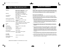
Section III Installation
LOCATION
Plan the location of the transceiver and microphone bracket before starting the in-
stallation. Select a location that is convenient for operation and does not interfere
with the driver or passengers in the vehicle. In automobiles, the transceiver is usu-
ally mounted below the dash panel, with the microphone bracket beside it.
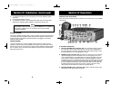
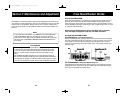
MOUNTING THE CONNECTION
The COBRA 148 GTL ST is supplied with a universal mounting bracket. When
mounting the bracket and radio to your car, make sure it is mechanically strong.
Also provide a good electrical connection to the chassis of the vehicle. Proceed as
follows to mount the transceiver:
1. After you have determined the most convenient location in your vehicle, hold
the COBRA 148 GTL ST with mounting bracket in the exact location desired. If
nothing will interfere with mounting it in the desired position, remove the
mounting bolts. Before drilling the holes, make sure nothing will interfere with
the installation of the mounting bolts.
2. Connect the antenna cable plug to the standard receptacle on the rear panel.
Most CB antennas are terminated with a type PL-259 plug and mate with the
receptacle.
3. Connect the red DC power input wire (with the fuse) to +13.8V DC. This wire
extends from the rear panel. In automobile installation, +13.8V DC is usually
obtained from the accessory contact on the ignition switch. This prevents the
set being left on accidentally when the driver leaves the car and also permits
operating the unit without the engine running. Locate the accessory contact on
most ignition switches by tracing the power wire from the AM broadcast receiv-
er in the car.
4. Connect the black lead to -13.8V DC. This is usually the chassis of the car. Any
convenient location with good electrical contact (remove paint) may be used.
5. Mount the microphone bracket on either side of the transceiver, using the two
screws supplied. When mounting in an automobile, place the bracket under the
dash so the microphone is readily accessible.
148.GTL.ST.MANUAL 10/1/98 10:56 AM Page 7