


Section I Introduction
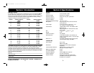
FREQUENCY RANGE
The COBRA 148 GTL ST transceiver represents one of the most advanced SSB/AM
two-way radios ever designed for use as a Class D station in the Citizens Radio
Service. This unit features advanced Phase Lock Loop (PLL) circuitry, which is used
in the AM mode and in the upper and lower single sideband modes, providing
complete coverage of all 40 channels shown below.
Channel Channel Frequency
in MHz
1 26.965
2 26.975
3 26.985
4 27.005
5 27.015
6 27.025
7 27.035
8 27.005
9 27.065
10 27.075
11 27.085
12 27.105
13 27.115
14 27.125
15 27.135
16 27.155
17 27.165
18 27.175
19 27.185
20 27.205
The COBRA 148 GTL ST has a vastly superior receiver which includes an RF gain
control and noise blanker circuitry effective in both AM and SSB modes., and an
automatic noise limiter effective in the AM mode. The receiver also features
increased protection against cross modulation and strong adjacent channel signals.
To obtain maximum performance please read carefully the descriptions and oper-
ating instructions in this manual.
Channel Channel Frequency
in MHz
21 27.215
22 27.225
23 27.255
24 27.235
25 27.245
26 27.265
27 27.275
28 27.285
29 27.295
30 27.305
31 27.315
32 27.325
33 27.335
34 27.345
35 27.355
36 27.365
37 27.375
38 27.385
39 27.395
40 27.405
2
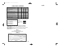
Serial No.
Date of Purchase
Dealer Name
Keep this manual for detailed information about your Cobra CB radio.
SAVE YOUR SALES RECEIPT, THE CARTON AND “PACKING” MATERIALS FOR
POSSIBLE FUTURE USE.
3
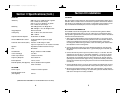
Section II Specifications
GENERAL
Channels 40 AM, 40LSB, 40 USB.
Frequency Range 26.965 to 27.405 MHz.
Frequency Control Phase Lock Loop (PLL) synthesizer.
Frequency Tolerance 0.005%
Frequency Stability 0.001%
Operating Temperature Range -30° C to + 50° C
Microphone Plug-in dynamic; with push-to-talk switch
and coiled cord.
Input Voltage 13.8V DC nominal, 15.9V max., 11.7V
min. (positive or negative ground).
Current Drain Transmit: AM full mod., 2.2A. SSB 12 watts
PEP output, 2A.
Receive: Squelched, 0.25A Maximum audio
output, 0.6A.
Size 2
3
/
8
”(H) x 7
7
/
8
”(W) x 9
1
/
4
”(D).
Weight 5 lbs.
Antenna Conductor UHF, S0239.
Semiconductors 3 field effect transistors, 45 transistors, 63
diodes, 6 integrated circuits, 1 two color light
emitting diode.
Meter (3-in-1) Illuminated; indicates relative output power,
received signal strength, and SWR.
TRANSMITTER
Power Output AM, 4 watts.
SSB, 12 watts, PEP.
Modulation High-and low-level Class B, Amplitude
Modulation.
Intermodulation Distortion SSB: 3rd order, more than -25 dB.
5th order, more than -35 dB.
SSB Carrier Suppression 55 dB.
Unwanted Sideband 50 dB.
Frequency Response AM and SSB; 300 to 2500 Hz.
Output Impedance 50 ohms, unbalanced
Output Indicators Meter shows relative RF output power
and SWR. Transmit LED glows red when
transmitter is in operation.
148.GTL.ST.MANUAL 10/1/98 10:56 AM Page 5