


Section IV Operation (Continued)
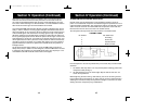
4. SWR CAL CONTROL (outer concentric dial). In order for you to achieve
maximum radiated power and the longest range, it is important that your
antenna be in good condition, properly adjusted and matched to your trans-
ceiver. The Built-in SWR (standing wave ratio) meter lets you easily measure
your antenna condition. To operate this function, connect your antenna to the
transceiver antenna output connector. Select a channel near the middle of the
band such as 21 or the channel you plan to use most frequently. Turn the
power on and set the meter function switch to the CAL position. Press and
hold the microphone push-to-talk button and using the SWR CAL control,
adjust the meter to read the CAL position indicated on the meter face. Then,
without releasing the microphone button, switch the meter function switch to
the SWR position and read the SWR indicated. The lower the figure, the bet-
ter, with 1 being ideal. Generally speaking, readings up to 3 are acceptable,
but over 3 indicates that you are losing radiated power and antenna adjust-
ment may be advisable.
5. DYNAMIKE. Adjusts the microphone gain in the transmit and PA modes. This
controls the gain to the extent that full talk power is available several inches
away from the microphone. In the Public Address (PA) mode the control
functions as the volume control.
6. VOICELOCK. Allows variation of the receiver operating frequencies above
and below the assigned frequency. Although this control is intended primarily
to tune in SSB signals, it may also be used to optimize AM signals as
described in the Operating Procedure paragraphs.
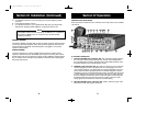
7. DIM/NOR/BRT SWITCH. Controls the brightness of the meter and LED chan-
nel indicator for optimum intensity for day or night-time driving.
8. CHANNEL SELECTOR. This switch selects any one of the forty Citizens Band
or 80 single side band channels desired. The selected channel appears on the
LED readout directly above the Channel Selector knob. Channel 9 has been
reserved by the FCC for emergency communications involving the immediate
safety of life of individuals or immediate protection of property. Channel 9
may also be used to render assistance to a motorist.
9. 0FF/ANL-NB/ANL SWITCH. In the ANL position only the automatic
noise limiter in the audio circuits is activated. When the switch is placed
in the ANL + NB position, the RF noise blanker also is activated. The
RF noise blanker is very effective for repetitive impulse noise such as
ignition interference.
10
Section IV Operation (Continued)
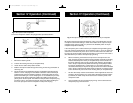
10. PA/CB SWITCH. Selects the mode of operation. In the CB position, the PA func-
tion is disabled and the unit will transmit and receive on the speaker that is con-
nected. In the PA mode, incoming CB transmission will be heard through the PA
s p e a k e r. This allows you to monitor messages while outside of your ve h i c l e .
To use the PA feature, a speaker having a voice coil impedance of 8 ohms and
a power handling capability of at least three watts should be used. This speak-
er must be plugged into the PA SPKR jack at the rear of the tra n s c e ive r. If the
public address feature is to be used primarily for outdoor applications, the use
of a weatherproof horn type public address speaker is recommended. Th e
d u rability of this type speaker plus the inherent efficiency of such a speaker
will provide more than adequate results when combined with the high audio
output level available from the COBRA 148 GTL ST. With the PA speaker con-
nected as outlined previously, be sure that there is physical separa t i o n
between the microphone and the speaker itself. If the speaker is located too
close to the microphone, acoustic feedback will result when the public
address system is operated at high volume. A directional type outdoor speaker
reduces the amount of isolation required. Some experimentation will deter-
mine the minimum amount of isolation required for a given sound level from
the public address system.
NOTE
PA volume is controlled by adjusting the DYNAMIKE knob to
the desired volume.
11. S - R F / CAL/SWR SWITCH. When in the S-RF position, the meter swings propor-
tionally to the strength of the received signal. When transmitting, the meter
indicates relative RF output pow e r.
When in the “CA L” position, the SWR meter can be calibrated by adjusting the
“SWR” control to the “CA L” mark on the meter face.
When in “SWR” position, the standing wave ratio is measured.
12. MODE (USB/AM/LSB) SWITCH. This sw i t ch is used to select AM, LSB or USB
mode of operation. Unless the station with wh i ch communication is desired is
equipped with SSB, the AM mode is normally used. The mode selector sw i t ch
changes the mode of operation of both transmitter and receiver simultaneous-
l y. Turn to “Receiving SSB signals” for a further explanation of single sideband.
13. TONE SWITCH HI/NOR/LOW. This switch is used to shape the audio
response to the operator’s preference. Bass is increased in the LOW position
and treble is increased in the HI position.
14. SOUNDTRACKER
™
SWITCH. Depressing this button turns on the SoundTracker
system in your CB.
11
148.GTL.ST.MANUAL 10/1/98 10:56 AM Page 13