


Section III Installation (Continued)
D. Try a different location on your car (keeping in mind the radiation pattern
you wish).
E. Is the antenna perfectly vertical?
F. Try a different location in your neighborhood. Stay away from large metal
objects when adjusting (metal telephone or light posts, fences, etc.).
NOTE
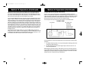
The COBRA 148 GTL ST will operate into an SWR of 2 to 1 indefinitely
and sustain an SWR of 20:1 for a maximum of 5 minutes at rated
operating conditions.
EXTERNAL SPEAKER
The external speaker jack (EXT. SPK.) on the rear panel is used for remote receiver
monitoring. The external speaker should have 8 ohms impedance and be able to
handle at least 4 watts. When the external speaker is plugged in, the internal
speaker is disconnected.
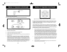
PUBLIC ADDRESS
To use the transceiver as a public address system connect an external 8 ohm
speaker (4 watts minimum) to the PA SPK. jack located on the rear panel. Direct
speaker away from the microphone to prevent acoustic feedback. Physical separa-
tion or isolation of the microphone and speaker is important when operating the
PA at high output levels.
8
9
Section IV Operation
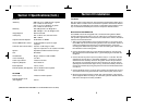
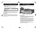
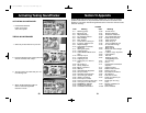
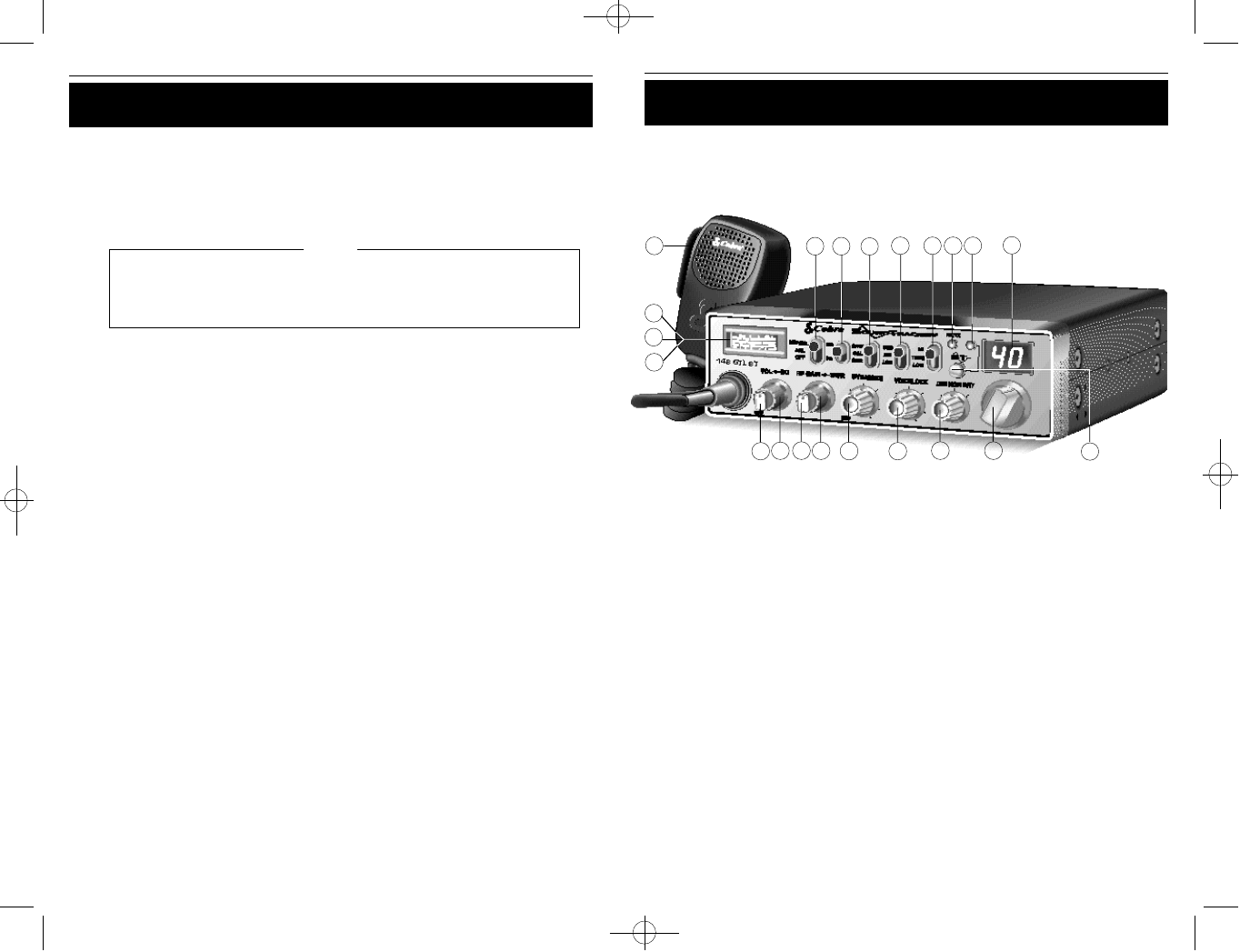
CONTROLS AND INDICATORS
There are fourteen controls and four indicators on the front panel of your COBRA
148 GTL ST.
A. CONTROL FUNCTIONS
1. OFF/ON/VOLUME (inner concentric dial). Turn clockwise to apply power to
the unit and to set the desired listening level. During normal CB operation,
the VOLUME control is used to adjust the output level obtained either at the
transceiver speaker or the external speaker, if used.
2. SQUELCH (outer concentric dial). This control is used to cut off or eliminate
receiver background noise in the absence of an incoming signal. For maxi-
mum receiver sensitivity it is desired that the control be adjusted only to the
point where the receiver background noise or ambient background noise is
eliminated. Turn fully counterclockwise then slowly clockwise until the receiv-
er noise disappears. Any signal to be received must now be slightly stronger
than the average received noise. Further clockwise rotation will increase the
threshold level which a signal must overcome in order to be heard. Only
strong signals will be heard at a maximum clockwise setting.
3. RF GAIN CONTROL (inner concentric dial). Used to reduce the gain of the
RF amplifier under strong signal conditions.
1
2
3
5
6
4
7 8
9
21
10
11
12 13
15
16
17
18
14
19 20
148.GTL.ST.MANUAL 10/1/98 10:56 AM Page 11