


12
Section IV Operation (Continued)
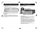
B. INDICATOR FUNCTIONS
15. S-METER. Swings proportionally to the strength of the incoming signal.
16. RF METER. Swings proportionally to the RF output power.
17. SWR METER. Swings proportionally to the ratio of standing wave voltage and RF
output. Used to properly adjusts the length of the antenna, and to monitor the qual-
ity of the coaxial cable and all RF electrical connections. If there is any degra d a t i o n
wh a t s o e ver in any of the above, due to humidity, salt, spray, vibration or corrosion,
the SWR meter reading will rise, thereby indicating that a problem exists.
To calibrate, sw i t c h to the “CA L” position, transmit in AM Mode by pressing the (PTT)
mic sw i t ch, and adjust the SWR control to the “CA L” mark on the meter then sw i t ch
to “SWR” position for the SWR measurement (Note: CB must be in AM mode).
18. CHANNEL INDICATOR. Numbered LED indicates the selected channel you
wish to operate on.
19. RECEIVE/TRANSMIT INDICATOR. The receiver/transmit LED indicator is
located next to the channel indicator. When in receive, the LED will be
green. When in transmit the LED will be red.
20. S O U N D T R ACKER™ INDICATO R . A red LED will illuminate when the
SoundTracker system is engaged on your CB.
21. PRESS-TO-TALK MICROPHONE.The receiver and transmitter are controlled
by the Press-To-Talk switch on the microphone. Press the switch and the
transmitter is activated, release the switch to receive. When transmitting, hold
the microphone two inches from the mouth and speak clearly in a normal
“voice”. The radio comes complete with low-impedance (500 ohm) dynamic
microphone. For installation instructions on the other microphones see
ALTERNATE MICROPHONES AND INSTALLATION section.
OPERATING PROCEDURE TO RECEIVE
1. Be sure that the power source, microphone and antenna are connected to the
proper connectors before going to the next step.
2. Set PA-CB Switch to the CB position and turn unit on by turning VOL control
clockwise on COBRA 148 GTL ST.
3. Set the VOLUME for a comfortable listening level.
4. Set MODE switch to the desired mode.
5. Set the RF gain control fully clockwise for maximum RF gain.
6. Listen to the background noise from the speaker.Turn the SQUELCH control
slowly clockwise until the noise JUST disappears (no signal should be pre-
sent). Leave the control at this setting. The SQUELCH is now properly adjust-
ed. The receiver will remain quiet until a signal is actually received. Do not
advance the control too far, or some of the weaker signals will not be heard.
7. Set the CHANNEL selector switch to the desired channel.
8. Adjust the VOICE LOCK control to clarify the SSB signals or to optimize
AM signals.
13
Section IV Operation (Continued)
OPERATING PROCEDURE TO TRANSMIT
1. Select the desired channel of transmission.
2. Set the DYNAMIKE control fully clockwise.
3. If the channel is clear, depress the Push-To-Talk switch on the microphone
and speak in a normal voice.
RECEIVING SSB SIGNALS
There are three types of signals presently used for communications in the Citizens
Band: AM, USB, and LSB. When the MODE switch on your unit is placed in the
AM position, only standard double-sideband, full carrier signals will be detected.
An SSB signal may be recognized while in the AM mode by its characteristic
“Donald Duck” sound and the inability of the AM detector to produce an intelligi-
ble output. The USB and LSB modes will detect upper sideband and lower side-
band respectively, and standard AM signals.
SSB reception differs from standard AM reception in that SSB receiver does not
require a carrier or opposite sideband to produce an intelligible signal. A single-
sideband transmitted signal consists only of the upper or the lower sideband and
no carrier is transmitted. The elimination of the carrier from the AM signal helps to
eliminate the biggest cause of whistles and tones heard on channels which make
even moderately strong AM signals unreadable. Also, SSB takes only half of an AM
channel, therefore two SSB conversations will fit into each channel expanding the
40 AM channels to 80 SSB channels. The reduction in channel space required also
helps in the receiver because only half of the noise and interference can be
received with 100% of the SSB signal.
An SSB signal may be received only when the listening receiver is functioning in
the same mode. In other words, an upper sideband signal (USB) may be made
intelligible only if the receiver is functioning in the USB position.
If a lower sideband (LSB) signal is heard when the receiver is in the USB mode,
no amount of tuning will make the signal intelligible. The reason for this may be
understood if you consider that when the modulation is applied to the transmit-
ter’s microphone in the USB mode, the transmitter’s output frequency is increased
whereas in the LSB mode the transmitter’s output frequency is decreased. The
result in listening to the receiver is that when the MODE switch is in the proper
position (either USB or LSB), a true reproduction of single tone of modulation will
result, and if the tone is increased in frequency (such as a low-pitched whistle or a
high-pitched whistle) you will hear the increase in the output tone of the receiver.
If the incorrect mode is selected, an increase in tone of a whistle applied to the
transmitter will cause a decrease in the resultant tone from the receiver.
148.GTL.ST.MANUAL 10/1/98 10:56 AM Page 15