


16
3
4
2
1
Section IV Operation (Continued)
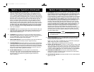
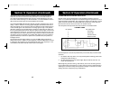
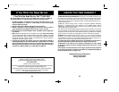
Fig. 2. Microphone Cable Preparation
To wire the microphone cable to the plug provided, proceed as follows.
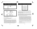
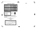
Fig. 3. Microphone plug wiring.
1. Remove the retaining screw.
2. Unscrew the housing from the pin receptacle body.
3. Loosen the two cable clamp retainer screws.
4. Feed the microphone cable through the housing, knurled ring and washer as
shown Fig. 3B.
5. The wires must now be soldered to the pins as indicated in the above wiring
tables. If a vise or clamping tool is available it should be used to hold the pin
receptacle body during the soldering operation, so that both hands are free to
perform the soldering. If a vise or clamping tool is not available, the pin recep-
tacle body can be held in a stationary position by inserting it into the micro-
phone jack on the front panel. The numbers of the pins of the microphone plug
are shown in Fig 4, as viewed from the back of the plug. Before soldering the
wire to the pins, pre-tin the wire receptacle of each pin of the plug.
17
Section IV Operation (Continued)
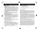
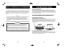
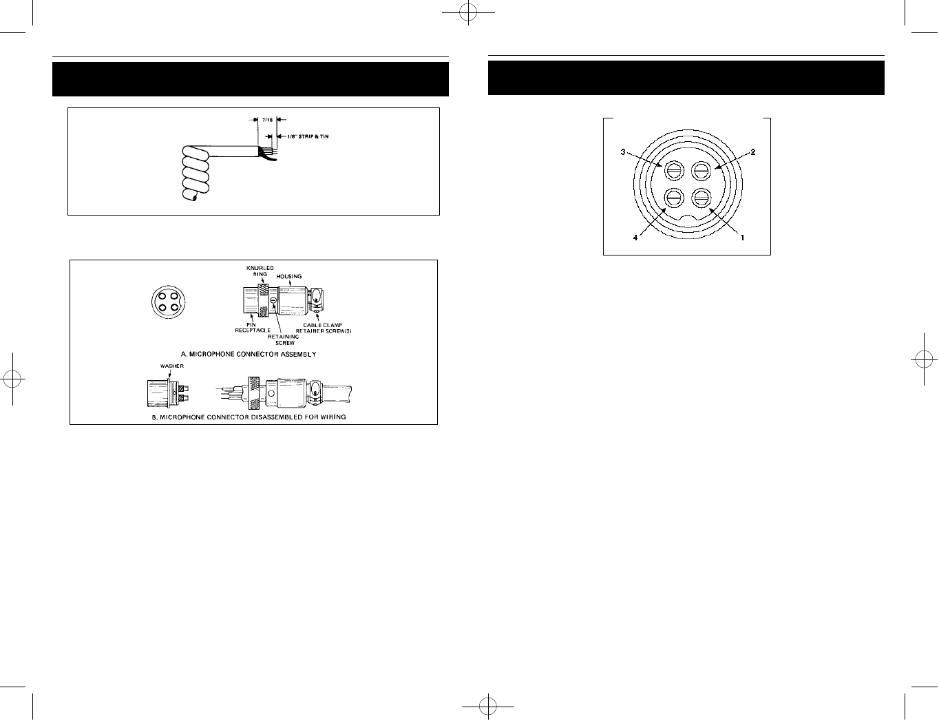
Fig. 4. Microphone plug pin numbers viewed from rear of pin receptacle.
Be sure that the housing and the knurled ring of Fig. 3 are pushed back onto the
microphone cable before starting to solder. If the washer is not captive to the pin
receptacle body, make sure that it is placed on the threaded portion of the pin
receptacle body before soldering.
If the microphone jack is used to hold the pin receptacle during soldering opera-
tion, best results are obtained when the connections to pins 1 and 3 are made first
and then the connections to pins 2 and 4. Use a minimum amount of solder and
be careful to prevent excessive solder accumulation on pins, which could cause a
short between the pin and the microphone plug housing.
6. When all soldering connections to the pins of the microphone are com-
plete, push the knurled ring and the housing forward and screw the housing
onto the threaded portion of the pin receptacle body. Note the location of
the screw clearance hole in the plug housing with respect to the threaded
hole in the pin receptacle body. When the housing is completely threaded
into the pin receptacle body, a final fraction of a turn either clockwise or
counterclockwise may be required to align the screw hole with the threaded
hole in the pin receptacle body. When these are aligned, the retaining screw
is then screwed into place to secure the housing to the pin receptacle body.
7. The two cable clamp retainer screws should now be tightened to secure the
housing to the microphone cord. If the cutting directions have been careful-
ly followed, the cable clamp should secure to the insulation jacket of the
microphone cable.
8. Upon completion of the microphone plug wiring, connect and secure the
microphone plug in the transceiver.
148.GTL.ST.MANUAL 10/1/98 10:56 AM Page 19