


3-11
Cisco VG202, Cisco VG202XM, Cisco VG204, and Cisco VG204XM Voice Gateways Hardware Installation Guide
OL-15959-01
Chapter 3 Installing the Voice Gateway
Connecting Cables
Procedure
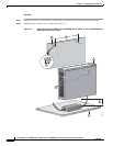
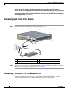
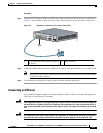
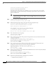
Step 1 Connect the RJ-45 end of a DB-9–to–RJ-45 serial cable to the RJ-45 Console Aux port on the chassis.
Figure 3-7 shows the RJ-45 end of the serial cable connected to the Console Aux port on the chassis.
Figure 3-7 Connecting a Terminal or PC to the Console Port
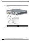
Step 2
Connect the DB-9 end of the RJ-45–to–DB-9 serial cable to the to the COM port on your laptop or PC.
Note Some laptops and personal computers do not have DB-9 serial port connectors and may require
a USB to serial port adapter.
Step 3 To communicate with the voice gateway, begin a terminal emulator application.
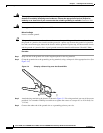
Connecting an FXS Line
Use a standard straight-through RJ-11 modular telephone cable to connect a Foreign Exchange Service
(FXS) port to a telephone or fax machine.
Warning
This equipment contains a ring signal generator (ringer), which is a source of hazardous voltage. Do
not touch the RJ-11 (phone) port wires (conductors), the conductors of a cable connected to the RJ-11
port, or the associated circuit-board when the ringer is active. The ringer is activated by an incoming
call.
Warning
For connections outside the building where the equipment is installed, the following ports must be
connected through an approved network termination unit with integral circuit protection: FXS.
1 RJ-45 connector to the Console Aux port on
the chassis
2 DB-9 connector
VG204
12V
D
C
S
A
CONSOLE
AUX
FastE
the
r
n
et
0/1
0
/0
FXS
0/
1
0
/
20
/
3
0/0
2
1
272270