


3-10
Cisco VG202, Cisco VG202XM, Cisco VG204, and Cisco VG204XM Voice Gateways Hardware Installation Guide
OL-15959-01
Chapter 3 Installing the Voice Gateway
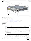
Connecting Cables
crosses. On-premise wiring is protected from power line crosses by a device that provides
overcurrent and overvoltage protection. Nevertheless, if the on-premise wiring is in close proximity
to, or not shielded from, the off-premise wiring or power cables during a lightning strike or power
surge, the on-premise wiring can carry a dangerous discharge to the attached interface, equipment,
and nearby personnel.
Statement 338
Connecting Input Power to the Chassis
Procedure
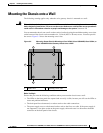
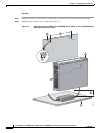
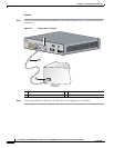
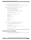
Step 1 Connect the chassis to an AC power outlet as shown in Figure 3-6.
Figure 3-6 Connecting the External Power Supply to the Cisco Voice Gateway
Step 2
To secure the power cord to the voice gateway, attach the power lock clip to the power cord, and slide
the clip to the end of the DC plug. See location 1 in Figure 3-6.
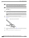
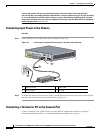
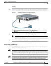
Connecting a Terminal or PC to the Console Port
Connect a terminal or PC to the Console Aux port either to configure the software by using the
command-line interface (CLI) or to troubleshoot problems with the voice gateway.
1 Power lock clip 2 Power cord
3 Power adapter 4 AC plug
VG204
12V D
C S
A
CO
N
SOL
E
AU
X
FastEthernet
0/1
0/0
FXS
0/1
0/
20/3
0/0
272269
1
2
4
3