


3-5
Cisco VG202, Cisco VG202XM, Cisco VG204, and Cisco VG204XM Voice Gateways Hardware Installation Guide
OL-15959-01
Chapter 3 Installing the Voice Gateway
Mounting the Chassis onto a Wall
Mounting the Chassis onto a Wall
The following warning applies only when the voice gateway chassis is mounted on a wall:
Warning
This unit is intended to be mounted on a wall. Please read the wall-mounting instructions carefully
before beginning installation. Failure to use the correct hardware or to follow the correct procedures
could result in a hazardous situation to people and damage to the system.
Statement 248
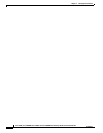
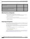
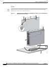
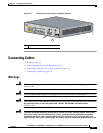
You can mount the chassis onto a wall or other vertical surface by using the molded mounting-screw slots
on the bottom of the chassis and two number-six, 3/4 inch (M3.5 x 20 mm) screws. You must provide
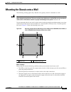
the screws. Figure 3-2 shows the mounting-screw slots.
Figure 3-2 Mounting-Screw Slots for Mounting a Cisco VG202, Cisco VG202XM, Cisco VG204, or
Cisco VG204XM Voice Gateway Chassis onto a Wall
Before You Begin
Ensure that you meet the following conditions when you mount the chassis onto a wall:
• The LEDs on the front panel face upward and are easily visible, because you will use the LEDs as
status and problem indicators.
• The back panel faces downward, to reduce strain on the cable connections.
• The power supply rests on a horizontal surface such as the floor or a table. If the power supply is
not supported, it can place strain on the power supply cable and cause it to disconnect from the
connector on the back panel of the chassis.
1 Rubber feet 2 Mounting-screw slots
231984
1
1
1
1
2
2