


3-8
Cisco VG202, Cisco VG202XM, Cisco VG204, and Cisco VG204XM Voice Gateways Hardware Installation Guide
OL-15959-01
Chapter 3 Installing the Voice Gateway
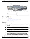
Installing the Ground Connection
Warning
This equipment must be grounded. Never defeat the ground conductor or operate the equipment in the
absence of a suitably installed ground conductor. Contact the appropriate electrical inspection
authority or an electrician if you are uncertain that suitable grounding is available.
Statement 1024
Warning
Use copper conductors only.
Statement 1025
Before You Begin
Locate a suitable ground.
Tip Using a multimeter, measure the resistance between various possible ground locations, such as between
the ground of a junction box (outlet) and the ground of a power tap, between the ground of a junction
box and a metal water pipe, between the chassis and the ground of a power tap, and between the chassis
and the ground of a junction box. A good ground connection should read between 0.0 and 0.5 Ohm.
Procedure
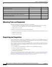
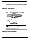
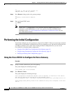
Step 1 Strip one end of the ground wire to the length required for the ring terminal.
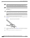
Step 2 Crimp the ground wire to the ground lug or ring terminal, using a crimp tool of the appropriate size. (See
Figure 3-4.)
Figure 3-4 Crimping a Ground Lug onto the Ground Wire
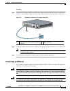
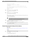
Step 3
Attach the ring terminal to the chassis as shown in Figure 3-5. For a ring terminal, use one of the screws
provided. Use a number 2 Phillips screwdriver to tighten the screws to a torque of 8 to 10 in-lb (0.9 to
1.1 N-m).
Step 4 Connect the other end of the ground wire to a grounding point at your site.
10360