


3-7
Cisco VG202, Cisco VG202XM, Cisco VG204, and Cisco VG204XM Voice Gateways Hardware Installation Guide
OL-15959-01
Chapter 3 Installing the Voice Gateway
Setting the Chassis on a Desktop
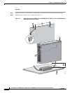
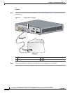
Step 3 Place the power supply on a horizontal surface.
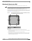
Caution If you are mounting the voice gateway on drywall, use hollow-wall anchors (1/8 inch with 5/16-inch drill
bit, or M3 with 8-mm drill bit) to secure the screws. If the screws are not properly anchored, the strain
of the network cable connections could pull the voice gateway from the wall. Use two wall anchors with
washers. Wall anchors and washers must be size number 10.
Setting the Chassis on a Desktop
You can place the voice gateway chassis on a desktop or shelf.
Caution Do not place anything on top of the chassis that weighs more than 10 lb (4.5 kg). Excessive weight on
top can damage the chassis.
Procedure
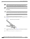
Step 1 Place the four rubber feet (from the accessory kit) in the four indentations on the underside of the chassis.
This helps provide proper airflow through and around the chassis.
Step 2 Place the chassis onto a smooth, flat surface.
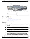
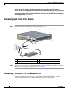
Installing the Ground Connection
You must connect the chassis to a reliable earth ground; the ground wire must be installed in accordance
with local electrical safety standards.
• For NEC-compliant grounding, use size AWG 14 (2 mm2) or larger wire and an appropriate
user-supplied ring terminal.
• For EN/IEC 60950-compliant grounding, use size AWG 18 (1 mm2) or larger wire and an
appropriate user-supplied ring terminal.
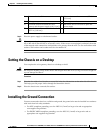
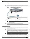
1 Two number-six, 3/4-in. screws 2 Distance between the two screws (5 7/16 in.
[13.8 cm])
3 Voice gateway 4 Mounting-screw slots
5 Maximum distance between the voice
gateway and the power supply (6 ft [1.8 m])
6 Horizontal surface on which to place the
power supply
7 Distance between the screw and the wall
(5/32 in. [0.40 cm])