


3-4
Cisco VG202, Cisco VG202XM, Cisco VG204, and Cisco VG204XM Voice Gateways Hardware Installation Guide
OL-15959-01
Chapter 3 Installing the Voice Gateway
Mounting Tools and Equipment
Mounting Tools and Equipment
Obtain the following tools and parts to install your voice gateway:
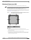
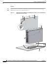
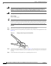
• Screws and anchors for mounting the chassis on the wall. You need eight wood screws or other
fasteners. You can use an additional starter screw to facilitate the wall-mounting.
• ESD-preventive wrist strap
In addition, you might need the following external equipment:
• Console terminal or personal computer with terminal emulation software for administrative access
• Modem for remote access
• Analog voice RJ-11 cable
Unpacking and Inspection
Do not unpack the Cisco VG202, Cisco VG202XM, Cisco VG204, or Cisco VG204XM voice gateway
until you are ready to install the equipment. If the installation site is not ready, keep the voice gateway
in its shipping container to prevent accidental damage.
The voice gateway, cables, and any optional equipment that you ordered might be shipped in more than
one box. When you unpack each shipping container, check the packing list to ensure that you received
all the following items:
• Cisco VG202, Cisco VG202XM, Cisco VG204, or Cisco VG204XM voice gateway
• Power cord, 6 feet (1.8-meters long)
• RJ-45-to-DB-25 adapter cable (labeled Console)
• Grounding lug and fasteners
Inspect all items for shipping damage. If anything appears damaged, or if you encounter problems when
installing or configuring your system, contact a customer service representative. (See the “Obtaining
Documentation and Submitting a Service Request” section on page vii.)
Software version verified
Rack, desktop, or wall-mounting of voice gateway completed
Initial electrical connections established
ASCII terminal attached to console port
Modem attached to console port (for remote configuration)
Signal distance limits verified
Startup sequence steps completed
Initial operation verified
Task Verified by Date