


3-9
Cisco 8110 Broadband Network Termination Unit User Guide
78-11666-01
Chapter 3 Installation
Removable Power Supply
Connecting 8110-PS-DC
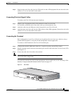
To connect your 8110-PS-DC DC Power Supply:
Step 1 Connect a minimum 14AWG ground wire to the stud located on the rear of the chassis. Fasten with a
lockwasher and screw.
Step 2 Remove the Dinkel connector from the unit
Step 3 Prepare a pair of 14 to 18 (16 recommended) AWG, cables
Step 4 Attach the -48VDC and the RTN connections to the Dinkel connector, and fasten them using the
connector screws. The polarity is detected automatically by the 8110-PS-DC.
Step 5 Snap the connector into the 8110-PS-DC Dinkel receptacle.
Power Supply Installation
This section contains the following:
• Table 3-2 Installing a Power Supply, page 3-9
• Removing a Power Supply, page 3-10
Installing a Power Supply
To install a power supply in your Cisco 8110:
Step 1 Verify that the module state is Out of Service (OOS), using the console or the in-band management
application.
Step 2 If you are installing a 8110-PS-220 verify that the input voltage selector strap, located in the right side
of the module, is in the right position
Step 3 Remove the Faceplate panel that covers the PS slot, if exists.
Step 4 Place the module's card edges into the right and left module guides at the rear of the Cisco 8110
Step 5 Slide in the module until it makes contact with the backplane, then push firmly to mate the connectors
solidly with the backplane.
Step 6 Secure the module's front panel to the Cisco 8110 chassis using the mounting screws on the right and
left of the module's front panel.
Step 7 Securely install and fasten each module to facilitate the installation of the one next to it.
Step 8 Snap the power cable
Step 9 Change the module state to active, using the console or the in-band management application.