


3-4
Cisco 8110 Broadband Network Termination Unit User Guide
78-11666-01
Chapter 3 Installation
Basic Hardware Features
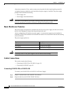
CIT Pinout
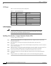
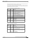
Table 3-1 shows the serial port pinout configuration.
LIM Modules
Caution The T1/E1 and T3/E3 connections are restricted to intra-building use only. Do not connect
to exposed plant. The equipment is intended to be used behind a CSU/DSU. The CSU/DSU
should be provided with adequate lightning protection.
Installing a Line Interface / Compact Subscriber Module (LIM)
To install a LIM in your Cisco 8110:
Step 1 Make sure that the LIM module state is OOS (Out Of Service) using the console, or the in-band
management application.
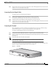
Step 2 Place the module’s card edges into the right and left module guides at the front of the
Cisco 8110
Step 3 Slide in the module until it makes contact with the backplane, then push firmly to mate the connectors
solidly with the backplane.
Step 4 When the module is seated solidly against the backplane, secure the module’s front panel to the Cisco
8110 chassis using the mounting screws on the right and left of the module’s front panel.
Step 5 Securely install and fasten each module to facilitate the installation of the one next to it.
Step 6 Configure the module type to the actual LIM type, using the console or the in-band management
application.
Step 7 Change the module state to Active, using the console or the in-band management application.
Table 3-1 Console Serial Port Pinout
Pin Number Signal Mnemonic Signal Name
1 DSR Data Set Ready
2 RXD Receive Data
3 TXD Transmit Data
4 DTR Data Terminal Ready
5 GND Signal Ground
6 DCD Data Carrier Detect
7 CTS Clear to Send
8 RTS Request to Send