


3-6
Cisco 8110 Broadband Network Termination Unit User Guide
78-11666-01
Chapter 3 Installation
Basic Hardware Features
Step 4 Attach the other end of the cable connected to the IN connector, to the timing source.
Step 5 If required, attach the other cable into the ETS OUT port on rear panel of the Cisco 8110 unit.
Step 6 Attach the other end of the cable connected to the OUT connector, to the input of the next equipment
requiring external timing.
Step 7 Set timing source to External timing.
Connecting the External alarms
The Cisco 8110 provides one external dry relay alarm indication, and four external alarm input
indications.
To connect your Cisco 8110 external alarm signals:
Step 1 Prepare a shielded cable with connector plug DB15 with shielded backshell.
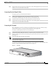
Step 2 Attach the D-type connector to the ALARMS port on the rear panel of your Cisco 8110 unit. To secure,
tighten the screws on both sides of the connector.
Step 3 Attach the other end of the cable connected to the alarm collection panel.
Step 4 Set the Alarm state to Active.
Note Refer to ”External Alarm Configuration” (Chapter 10) for information on using the console
management software for basic external alarms configuration.