


3-10
Cisco 8110 Broadband Network Termination Unit User Guide
78-11666-01
Chapter 3 Installation
General Operating Procedures
Removing a Power Supply
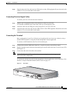
To remove a power supply from your Cisco 8110:
Step 1 Change the module state to Out Of Service (OOS) using the console, or the in band management
application
Step 2 2. Remove the power cable
Step 3 3. Unscrew the right and left mounting screws on the front panel of the module.
Step 4 4. Remove the module by pulling its handle.
Step 5 5. Use faceplate panels to protect unused slots from dust and reduce electromagnetic radiation.
Caution The Cisco 8110 ventilation mechanism is not effective if empty slots are not covered with
faceplate panels.
Caution Power cable should always be removed from module before unit is removed from Cisco
8110.
Caution If you store modules outside the Cisco 8110 for an extended period of time, place them in
the original packaging (or equivalent packaging providing ESD protection).
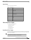
Power Supply LEDs
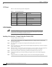
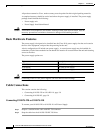
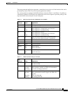
Table 3-3 shows the LEDs for the power supply.
General Operating Procedures
The operation of the Cisco 8110 can be controlled and monitored by the system management application
and by the panel indicators.
Table 3-3 Cisco 8110 Front Panel PS LEDs
LED Indicator Status Explanation
PS1 Off
On
Blink
PS in slot 1 Out Of Service
PS in slot 1 Active.
PS in slot 1 failed.
PS2 Off
On
Blink
PS in slot 2 Out Of Service
PS in slot 2 Active.
PS in slot 2 failed.