


3-11
Cisco 8110 Broadband Network Termination Unit User Guide
78-11666-01
Chapter 3 Installation
General Operating Procedures
The menu-generated application represents a centralized access point to all the functions that can be
performed by means of the Cisco 8110 System application software.
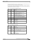
The various panels are equipped with LED indicators (shown in Table 3-4 and Table 3-5) which are
continuously updated in accordance with information received in response to periodic polling of the
traps and alarms received by the Cisco 8110 System.
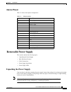
Table 3-4 Main Front Panel Section LEDsModel Cisco 8110RFE
LED
Indicator Status Explanation
Power On Unit is powered up
PS1 On
Off
Blink
Power Supply #1 is active
Power Supply #1 is intentionally out of service
Power Supply #1 is malfunctioning
PS2 On
Off
Blink
Power Supply #2 is active
Power Supply #2 is intentionally out of service
Power Supply #2 is malfunctioning
Run On Lights 20 seconds after power up, indicating that
software has been loaded and unit is operational
Tx ON Ethernet data transmit
Rx ON Data received
COL Blinks Collision detected
LED #1 ON
OFF
Port #1 link up
Port #1 link down
LED #2 ON
OFF
Port #2 link up
Port #2 link down
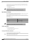
Table 3-5 LIM Front Panel LEDs for all models
LED
Indicator Status Explanation
ALM On
Off
Alarm present in LIM.
No alarm in LIM.
Tx Off
On Weak
On Strong
No cells transmitted in LIM port.
LIM transmitter enabled, no ATM cells transmitted
User cells are being transmitted.
Rx Off
On Weak
On strong
Flashing
No cells detected in LIM port.
LIM synchronized to receivd signal. No ATM cells
detected
ATM cells detected.
Error during Self Test