


3-3
Cisco 8110 Broadband Network Termination Unit User Guide
78-11666-01
Chapter 3 Installation
Basic Hardware Features
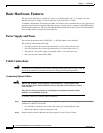
Step 3 Snap the other end of the cable into the ATM switch or other ATM equipment. Be sure that each cable
connects to Tx on one end and Rx on the other.
Connecting Electrical Signal Cables
To connect your Cisco 8110 unit electrical interfaces:
Step 1 Prepare a pair of appropriate cables with connectors on the Cisco 8110 side
It is advisable to mark the ends of the cable so that you can identify the wires.
Step 2 Attach the cables into the LIM ports on the front panel of your Cisco 8110 unit.
Step 3 Attach the other end of the cable into the ATM switch or other ATM equipment. Ensure that each cable
connects to Tx on one end and Rx on the other.
Connecting the Terminal
Basic configuration of your Cisco 8110 unit can be performed in one of two ways: either by using a
standard ASCII terminal, or using the in-band management software application.
To connect an ASCII terminal to the Cisco 8110 terminal port:
Step 1 Configure the terminal: 9600 baud, 8 data bits, 1 stop bit, no parity, xon/xoff flow control.
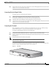
Step 2 Plug the included console cable into the terminal port located at the back of the Cisco 8110 unit (CIT).
(See Figure 3-1).
Step 3 Connect the other end of the cable to the terminal.
Note Refer to Configuration in Chapter 4 for information on using the console management
software for basic configuration.
To connect the terminal using the in-band management software application, see the“Installing a Line
Interface / Compact Subscriber Module (LIM)” section on page 3-4.
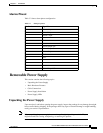
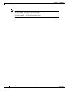
Figure 3-1 Rear Panel
8110-PS-110
ALARMS
CIT
ETS
IN
PS2
PS1
OUT
49400