


3-2
Cisco 8110 Broadband Network Termination Unit User Guide
78-11666-01
Chapter 3 Installation
Basic Hardware Features
Basic Hardware Features
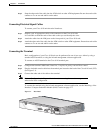
The unit can be fitted into a standard 19” rack or as a desktop and is 2.6” (1.5U high). For rack
mounting, the unit is simply screwed to the sides of the rack with 2 x 2 bolts.
A standard configuration will include two LIMs. To insert or extract a module into its slot, grip the two
mounting screws on the front panel and push to insert, or pull to extract. A network-side LIM should be
installed in the middle slot. The user-side LIM should be installed in the left side slot. The third module,
a hot standby module is placed in the far-right slot.
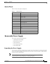
Power Supply and Fuses
The unit can be powered with 110/220VAC. A -48VDC option is also available.
The system is protected the following:
• For 220V products, the system is protected with a 1.25A slow-blow fuse (F1).
• For 110V products, the system is protected with a 2.5A slow-blow fuse (F1).
• The optional -48V power supply is protected with a 3.15A slow-blow fuse.
• Fuses are located in fuse holder (FH1).
Cable Connections
Caution All modules are susceptible to electrostatic discharge (ESD) even while installed. Take the
necessary precautions to minimize electrostatic damage while handling modules.
Connecting Optical Cables
Warning
When LIM-155SM-I ,LIM-155SM-L, LIM-155SM-XL, , LIM-155SM-I-SH,
LIM-155SM-L-SH or LIM-155SM-XL-SH are used the CISCO 8110 is a Class 1
Laser Product
Take the necessary precautions to avoid dangerous radiation hazards if these
modules are not handled properly.
To connect your Cisco 8110 unit optical interfaces:
Step 1 Prepare a pair of appropriate (multimode or singlemode) optical cables with appropriate (SC or ST)
connectors on the Cisco 8110 side.
• It is advisable to mark the ends of the cable so that you can identify the wires.
• Remove the optical connector protective cover.
Step 2 Snap the cables into the LIM ports on the front panel of your Cisco 8110 unit.