


3-7
Cisco 8110 Broadband Network Termination Unit User Guide
78-11666-01
Chapter 3 Installation
Removable Power Supply
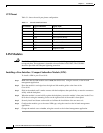
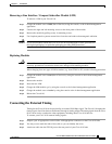
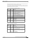
Alarms Pinout
Table 3-2 shows alarm pinout configuration
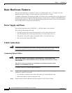
Removable Power Supply
This section contains the following topics:
• Unpacking the Power Supply
• Basic Hardware Features
• Cable Connections
• Power Supply Installation
• Power Supply LEDs
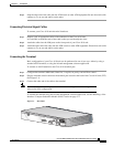
Unpacking the Power Supply
Upon receipt of, and before opening the power supply, inspect the package for any damage that might
have occurred during shipping. If the package shows any signs of external damage or rough handling,
notify your carrier's representative.
Note When unpacking the power supply be sure to keep all original packing materials. They
might be needed for storing, transporting, or returning the product.
Table 3-2 Alarm port pinout
Pin Number Signal Name
1 Alarm a input
2 Alarm b input
3 Alarm c input
4-
5 Gnd
6-
7 Alarm Output NO
8 Alarm Output Center
9 Alarm d input
10 Gnd
11 Gnd
12 -
13 -
14 -
15 Alarm Output NC