TS-100 Owner’s Manual
Telephone Usage
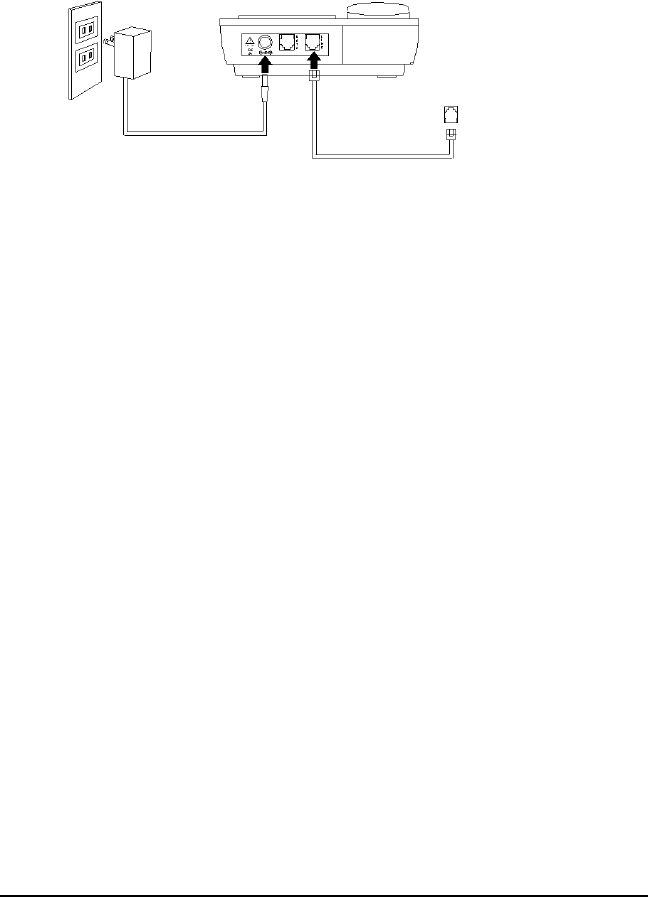
INSTALLATION
1. Connect the adapter. Plug the large part of the adapter into the wall outlet and the
adapter tip to the jack at the rear side of unit. (Use only 9V DC. 200mA, center positive
Class 2 adapter.)
2. Connect the telephone line cord.
a. To connect to TalkSwitch
• Use the new line cord to connect the LINE jack of your new caller ID phone to
the modular wall jack associated with your TalkSwitch extension.
b. To connect to a phone line.
• Use the existing line cord supplied to connect the LINE jack of your answering
machine to the wall modular line jack.
• Use the new line cord supplied to connect the telephone’s jack of your new
Caller ID phone to the PHONE jack of your answering machine.
• Set your answering machine to answer the phone after 2 or more rings.
3. Follow the procedure “Unit Setup” to set up your unit.
4. Place the unit on a flat table or mount it on a wall. If you desire to place it on a wall, use
the wall mount bracket and short line cord supplied to accomplish the wall mounting.
24/90V MESSAGE WAITING LAMP
If your phone is installed behind a different PBX than TalkSwitch, you will need to set the
MW switch in order to receive the Message Waiting indication.
TalkSwitch uses FSK Message Waiting Indicator. This light in the upper right
corner is not used for FSK Message Waiting Indicator. The green ‘Message’
indicator above the Caller ID display will light when new messages are left in
your voice mailbox.
1. To use with a different PBX, remove the directory cover by moving the holding clip up,
and pulling the clear cover up.
2. Once the directory cover is removed, locate the switch below the holding clip.
3. For 90V PBX Message Waiting Indication, move the switch to the position marked
“90V”. For 24V PBX Message Waiting Indication, move the switch to the position
marked “24V”. If connecting directly to telephone lines, move the switch to the center
“OFF” position. (See following page)
1


