


- 5 -
#6#1 #2 #3 #4 #5 #6#1 #2 #3 #4 #5 #6#1 #2 #3 #4 #5 #6#1 #2 #3 #4 #5
PS24
2
B
A
C
3
E
D
F
5
K
J
L
8
U
T
V
4
H
G
I
6
N
M
O
1
0
9
Y
X
W
Z
7
R
Q
P
S
2
B
A
C
1
7
R
Q
P
S
0
3
E
D
F
4
H
G
I
5
K
J
L
6
N
M
O
8
U
T
V
9
Y
X
W
Z
PS24
PS24
2
B
A
C
3
E
D
F
5
K
J
L
8
U
T
V
4
H
G
I
6
N
M
O
1
0
9
Y
X
W
Z
7
R
Q
P
S
2
B
A
C
1
7
R
Q
P
S
0
3
E
D
F
4
H
G
I
5
K
J
L
6
N
M
O
8
U
T
V
9
Y
X
W
Z
PS24
PS24
PS24
PS24
PS24
PS24
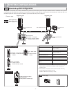
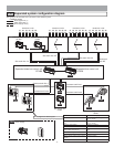
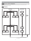
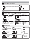
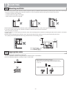
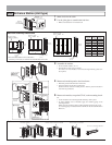
Common area
Residence trunks
* See page 4 for various types.
Power supply
Sub trunk line 1A
Common trunk line 2
Residence trunks
Sub trunk line 1B
Common trunk line 1
Residence trunks
Sub trunk line 2A
Common trunk line 1
Residence trunks
Sub trunk
line 2B
Common trunk line 2
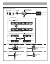
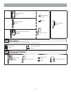
Audio signal line (1)
Video signal line (1)
Power supply line (1)
Expanded video bus control unit
GT-VBX
Expanded bus control unit
GT-BCX
Video bus control unit
GT-VBC
Bus control unit
GT-BC
Bus control unit
GT-BC
Entrance station
Security guard station
GT-MK
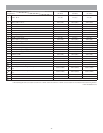
Capacity
Entrance station Maximum 16 stations (up to 8 sta-
tions per trunk)
Residential stations per sub trunk
line
Maximum 125 stations (up to 25 sta-
tions per trunk)
Security guard station Maximum 4 stations
Residential station Maximum 500 stations
Residential stations in the same resi-
dence (other than GT-2C)
Maximum 4 stations (2 monitor sta-
tions)
Bus control units per common trunk line
Maximum 1 unit
Bus
control units per sub trunk line Maximum 1 unit
Master stations in the same residence
(GT-2C)
Maximum station
Sub master monitor station Maximum 3 stations
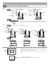
Expanded system configuration diagram1-2
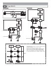
The wiring of the sub trunk line is the same as the standard system.