


- 24 -
4
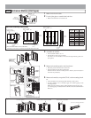
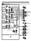
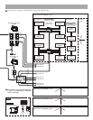
WIRING
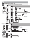
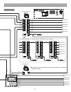
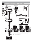
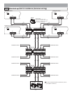
Standard system for common area4-1
#4
#5
#1
#2
GT-MK
GT-DMV/GT-DM
PS24
AC
AC
AC/DC
AC
NP
PT
PT
R1
R2
R1
R2
C
CE
+
-
R1
R2
R1
R2
C
CE
+
-
2
B
A
C
3
E
D
F
5
K
J
L
8
U
T
V
4
H
G
I
6
N
M
O
1
0
9
Y
X
W
Z
7
R
Q
P
S
2
B
A
C
1
7
R
Q
P
S
0
3
E
D
F
4
H
G
I
5
K
J
L
6
N
M
O
8
U
T
V
9
Y
X
W
Z
GT-10K
CN1
R1
R2
ELB
ELC
ELM
BP
BP
CN2
CN1
+
-
CN3
CN100
CN3
A2
A1
GT-VAGT-DA-L/GT-DAGT-NS-V/GT-NS
CN4CN6CN5
GT-10K
CN1
R1
R2
ELB
ELC
ELM
BP
BP
CN2
CN1
+
-
CN3
CN100
CN3
A2
A1
GT-VAGT-DA-L/GT-DAGT-NS-V/GT-NS
CN4CN6CN5
GT-10K
CN1
R1
R2
ELB
ELC
ELM
BP
BP
CN2
CN1
+
-
CN3
CN100
CN3
A2
A1
GT-VAGT-DA-L/GT-DAGT-NS-V/GT-NS
CN4
CN6CN5
A1
A2
R1
R2
ELB
ELC
ELM
BP
BP
+
-
CN2
A1
A2
R1
R2
ELB
ELC
ELM
BP
BP
+
-
CN2
VIGIK
AC/DC
AC
PT
PT
PS24
AC
VIGIK
AC
#1
#2
#3
1P
NP
NP
NP
NP
NP
NP
NP
PS24
AC
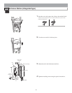
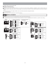
ON
1
2 3
4
#5
ON
1
2 3
4
#4
GT-DA-L/GT-DA
SW2: 2~4
ON
1
2 3
4
ON
1
2 3
4
ON
1
2 3
4
#3
#2#1
SW1: 2~4
ON
1
2 3
4
ON
1
2 3
4
#2#1
SW1: 4
* GT-NS-V only
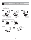
Orange (D+)
Brown NTSC (+)
DP
DP
DP
Brown NTSC (+)
Orange (D+)
* GT-DMV only
Yellow (D-)
Red NTSC (-)
Red NTSC (-)
Yellow (D-)
Blue
Blue
Green (GND)
Green (GND)
Purple
Purple
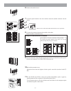
Less than AC/DC 24 V, 4 A
(resistance load)
PT: AC transformer
24 V
24 V
Less than AC/DC 24 V, 4 A
(resistance load)
PT: AC transformer
Entrance station #1 to #3
Ex.) Unit type
Surveillance camera
External door release button
External signaling relay
Door release
Door release
External
signaling relay
Doorbell
Surveillance camera
External door release button
Entrance station #4 to #5
Ex.) Integrated type
Security guard station
Entrance
station
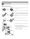
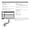
Put each piece of wiring in a separate sheath as shown in the diagram below.
NP:
Non-polarized