


- 31 -
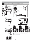
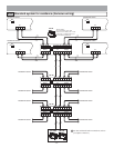
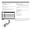
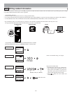
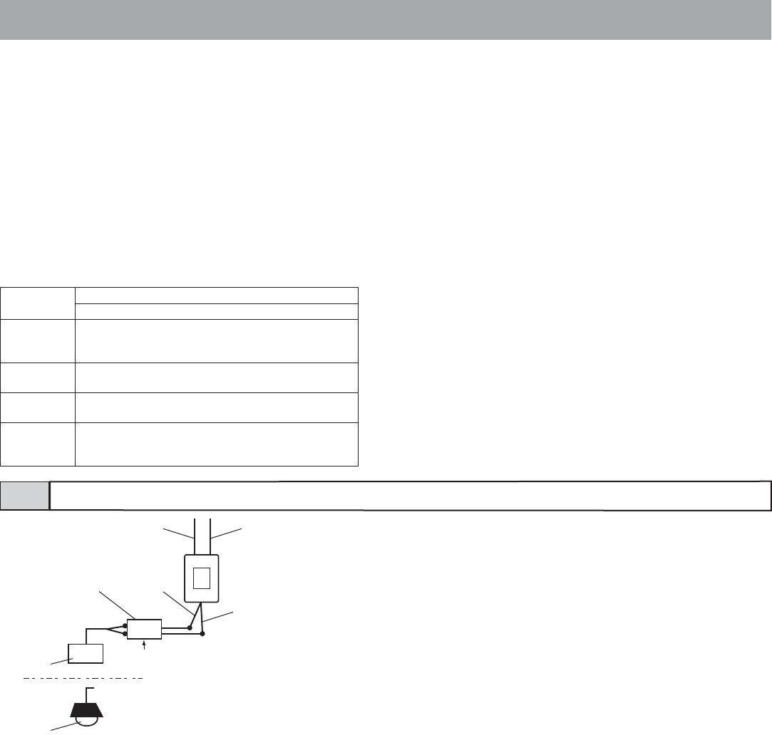
External signaling relay connection4-6
* When the GT-RY is connected, the separate option connecter (4-5) is re-
quired.
GT-RY contact specification: AC/DC 24 V, 0.5 A
AC
B
GT-RY
Lead wire (blue)
Lead wire (orange)Timer relay (not included)
Buzzer
Entrance
light
Lead wire (white)
Lead wire (orange)
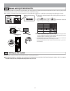
Emergency alarm
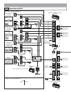
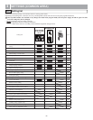
The emergency alarm switch can be connected.
N/C contact (locked type)
DC 12 V/0.1 A or higher
Call notification
Using the external signaling relay GT-RY allows for the external buzz-
er to be linked during calling.
Option contact output
External units such as lights can be operated with the option button.
Contact capacity: Maximum overload AC/DC 24 V, 1 A
Minimum overload DC 5 V, 100 mA
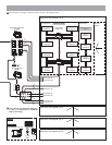
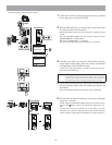
Security/Utility input 1 to 3
Input method
N/O or N/C dry closure contact
External sensor input (start signal only detection method)
Detection
confirmation
time
100 msec or more
Contact
resistance
N/O: 1 k or less/N/C: 50 k or more
Terminal short
current
1 mA or less
Voltage
between
terminals
DC 3.3 V or less (when open between terminals)
Video out
Video can be output to DVRs etc.
(NTSC, 1 Vp-p/75 ) Wiring distance: 3 m
NOTES: When a video signal is output, residential stations may pro-
duce a sound depending on the installation environment.
(The screen playing recorded pictures is not output.)
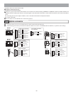
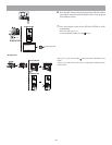
Display transfer
External monitors can be activated via the external signaling relay GT-
RY.
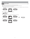
Doctor call (automatic entry)
This makes it possible to use the doctor call (automatic entry) function
at residential stations.
• GT-1C-L/GT-1C, GT-1M-L, GT-1A
Short the DC terminal.
• GT-1D
Cut (open) the jumper JP4.
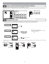
Doorbell
The doorbell can be connected.
N/O contact (non-locked type)
DC 12 V/0.1 A or higher