


- 16 -
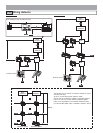
Entrance Station (Unit type)3-4
1
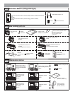
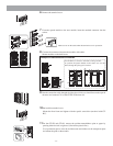
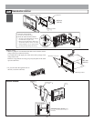
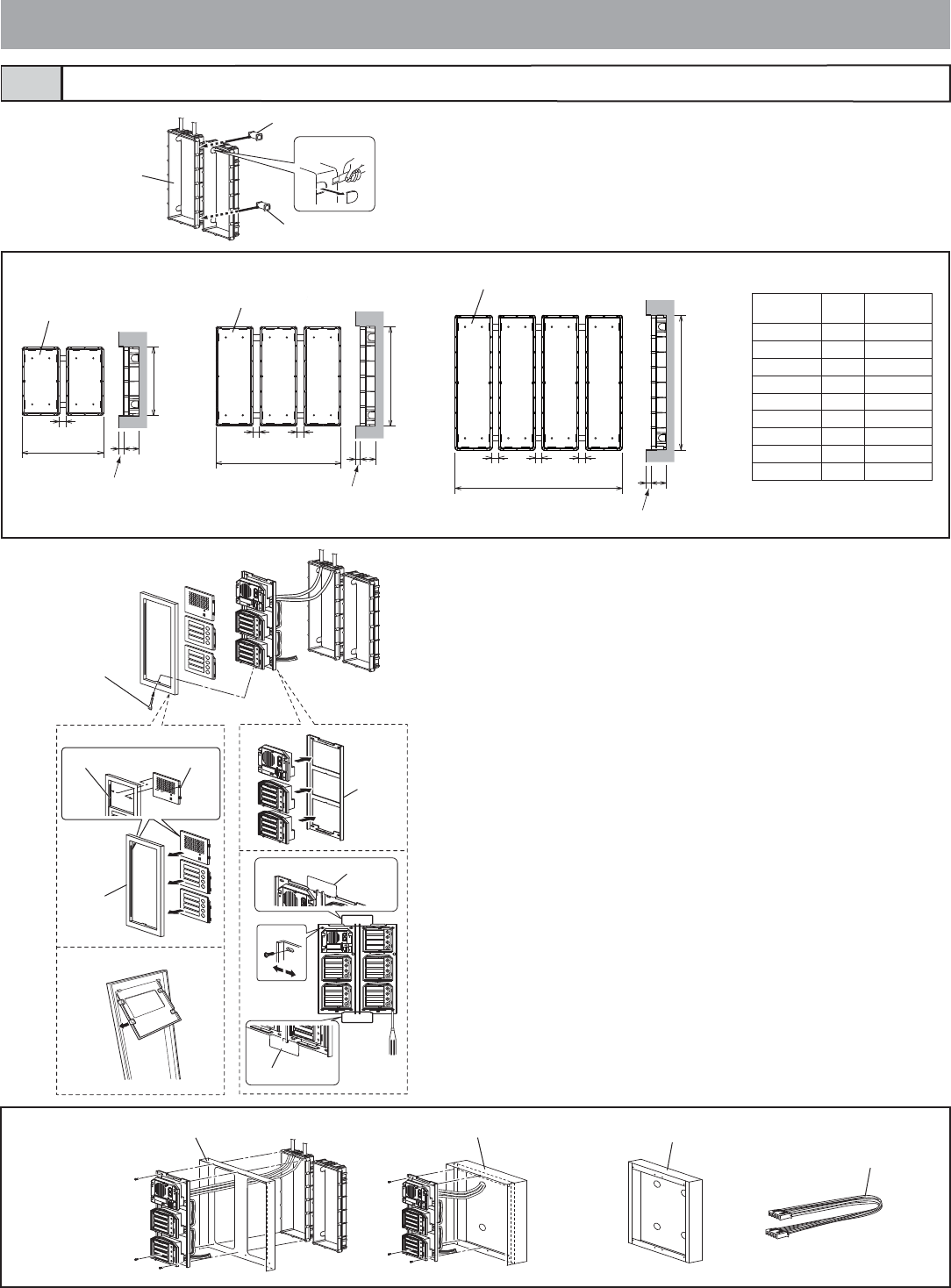
Make a hole for the cable.
2 Use the joint pipe to assemble the back box.
• Make sure the back box is mounted level.
Joint pipe
Joint pipe
Back box
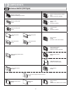
Options
Rain hood GT-203H
Surface-mount box GF-203BA
Hooded surface-mount box GT-203HB
80 cm (32") connection cable GF-C
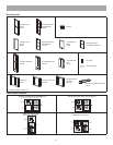
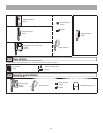
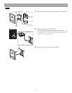
3 Assemble the module.
• For the useable modules, see 2-1.
• The GT-SW can have up to 6 modules.
To connect 7 or more modules or to increase the light intensity, please con-
tact Aiphone.
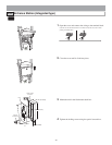
4 Mount each module panel to the front frame.
• Mount the panels from behind the front frame.
• Insert the holders into the slots on both sides.
(With the GT-4F, mount the module panels so that they catch on the tabs in
order from top to bottom.)
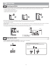
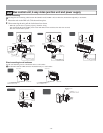
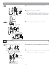
5 Mount each module, except the GT-AC, to the mounting brack-
et.
• Set the modules in the mounting bracket until they click in place.
• To mount multiple rows of modules, apply the mounting gauge to the
mounting bracket.
While using the mounting gauge to make adjustments, tighten the screws.
(A mounting gauge is included with the GF-2B, GF-3B, and GT-4B built-in
back box.)
Slot
GF-4F
Mounting
bracket
Mounting gauge
Mounting gauge
Holder
Special screwdriver
(enclosed with
GT-BC)
Front frame
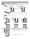
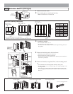
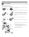
Back box assembly dimensions
*
*
*
* Do not mount the back box on a surface that is
recessed by 15 mm (1/2") or more from the external surface of the wall.
Back box GF-2B
25 mm
(1")
25 mm
(1")
25 mm
(1")
25 mm
(1")
25 mm
(1")
25 mm
(1")
W
W
W
15 mm
(9/16")
15 mm
(9/16")
15 mm
(9/16")
44 mm
(1-3/4")
44 mm
(1-3/4")
44 mm
(1-3/4")
200 mm
(7-7/8")
295 mm
(11-5/8")
400 mm
(15-3/4")
Back box GF-3B
Back box GT-4B
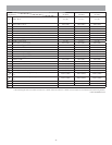
GF-2B/3B
GT-4B
W
(mm)
W
(inch)
x 1 110 4-5/16"
x 2 245 9-5/8"
x 3 380 15"
x 4 515 20-1/4"
x 5 650 25-9/16"
x 6 785 30-7/8"
x 7 920 36-1/4"
x 8 1055 41-9/16"
x 9 1190 46-7/8"