


ADCP-90-328 • Issue 2 • November 2005
Page 8
© 2005, ADC Telecommunications, Inc.
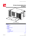
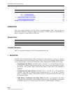
2 ACCESSORIES
The following accessory items may be ordered separately for FPL panels:
• Single and dual splice trays (for types, see Splice Type in Table 1 below)
• Additional kits for clamping and grounding cables
• Key locks for front and rear doors
• Buildout attenuators (ST and biconic)
• Bulkhead attenuators (ST, SC, D4, FC, and biconic)
3 SPECIFICATIONS AND DIMENSIONS
Table 1 lists specifications for the FPL modules.
Table 1. FPL Modules Specifications
PARAMETER SPECIFICATION
Common to All Panels
Rack mounting 19-inch (48.26 cm) or 23-inch (58.42 cm)
Hole spacing EIA or WECO
Recess options 4-inch (10.16 cm) or 5-inch (12.7 cm) recess
Connector types
Multimode SC, SC duplex, ST
©
, LX.5
©
, and LC;
Singlemode FC, FC (zirconia adapter), FC (8
o
polish), SC, SC (zirco-
nia adapter), SC (8
o
polish), SC duplex, ST
©
, ST
©
(zirconia adapter),
E-2000 (8
o
polish), E-2000 (flat polish), LX.5
©
, LC
Pigtail type Stranded or ribbon
Splice type Bare fusion, heat shrink fusion, mechanical, rotary, FibrLok, Raychem
Universal (R), Nortel, AFL
Pre-termination (optional) cable types Multimode IFC stranded 62.5/125;
Singlemode IFC stranded, IFC plenum stranded, OSP single armor
stranded, indoor-outdoor, OSP dielectric stranded, IFC Maxi-Strip,
IFC ribbon, OSP single armor ribbon, OSP dielectric ribbon
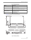
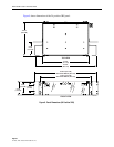
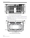
12/24 Position Panel (1RU)
Dimensions (H x W x D) 1.72 inch x 17.0 in. x 11.48 in.
(4.4 cm x 43.2 cm x 29.2 cm)
Capacity 12 or 24 termination positions
LX.5
©
and LC connectors double the termination capacity
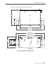
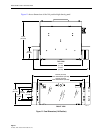
24 Position Panel (3RU)
Dimensions (H x W x D) 5.0 inch x 16.4 in. x 12.0 in.
(12.7 cm x 41.7 cm x 30.5 cm)
Capacity 24 termination positions
LX.5
©
and LC connectors double the termination capacity