


ADCP-90-328 • Issue 2 • November 2005
Page 15
© 2005, ADC Telecommunications, Inc.
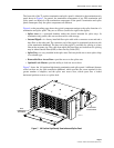
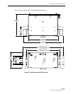
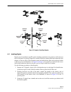
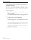
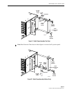
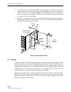
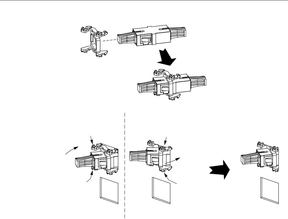
Figure 14. Example of Installing Adapters
5.2 Installing Pigtails
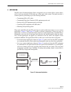
Pigtails may be installed in any FPL panel (including termination only panels) to utilize the rear
area of the panel for splicing. Pigtails are installed with the connectorized end connected to the
adapters on the rear side of the termination panel and with the bare fiber ends positioned within
a splice tray (for an illustration, see Figure 6 on Page 6). 3m pigtails are used with the excess
slack coiled within the chassis to provide a service loop for future use if needed.
Use the following procedure to install pigtails:
1. Separate out 12 pigtails. Apply a pair of designation tags to each pigtail for identification.
Attach one tag next to the connector and the other tag near the bare fiber end.
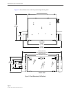
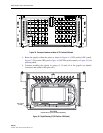
2. Working from the rear side of the panel, connect the pigtails to the interior side of
adapters/receptacles marked with the corresponding numbers. The connector numbers are
silk-screened on the interior side of the bulkhead, as shown in Figure 15 for the 72
position panel.
3. Group the 12 pigtails into a bundle and use the twist-lock fiber retainers provided to hold
the bundle together.
ROTATE AND
SNAP INTO
SLOT
COMPRESS
RELEASE
TABS
COMPRESS
RELEASE
TABS
ROTATE AND
SNAP INTO
SLOT
COMPRESS
RELEASE
TABS
COMPRESS
RELEASE
TABS
12
17846-A